- A MAC first half (that is, 24 bits) of a multicast MAC address (in hex) is 01-00-5e.
Converged network
- type of network combining voice, video, and data on the same network
- more cost effective than maintaining separate networks for each of these media types.
IP communications
- because voice traffic is latency-sensitive, the underlying network needs to be able to recognize voice traffic and treat it with high priority.
- involves sending video over IP networks (unique design and troubleshooting challenges that accompany video networks),
- many video networks heavily rely on IP multicast technologies.
Voice Troubleshooting
Voice over IP(VoIP) is used to describe the transmission of voice over an IP network using voice-enabled routers.
IP telephony refers to the use of IP phones and a call-processing server (for example, Cisco Unified Communications Manager)
More recently, Cisco began using the term Unified Communications, which encompasses more than just voice.
Unified communications includes a collection of applications and technologies that enhance user collaboration.
Overview of IP Telephony
An IP telephony network not only duplicates the features offered in traditional corporate Private Branch Exchange (PBX) systems, but IP telephony expands on those features:
- IP phone: provides IP voice to the desktop.
- Gatekeeper: provides call admission control (CAC), bandwidth control and management, and address translation features.
- Gateway: provides translation between VoIP and non-VoIP networks (PSTN), physical access for local analog and digital voice devices (telephones, fax and PBXs)
- Multipoint control unit (MCU): mixes audio and/or video streams, thus allowing participants in multiple locations to attend the same conference.
- Call agent:provides call control for IP phones, Call Admission Control (CAC), bandwidth control and management, and address translation. Although a call
agent could be server-based, Cisco also supports a router-based call agent, known as Cisco Unified Communications Manager Express(UCME).
- Application server: provides services such as voice mail, unified messaging, and presence information (which can show the availability of another user).
- Videoconference station:provides access for end-user participation in videoconferencing (device for video input and a microphone for audio input). Cisco targets its Cisco Unified Video Advantage product at desktop videoconferencing applications.
 |
| IP Telephony Components |
- Voice traffic needs to be treated in a special way, where it has higher priority than many other traffic types.
- Unlike much data traffic, voice traffic is highly latency-sensitive and drop-sensitive.
- Delay is the time required for a packet to travel from its source to its destination.
- Jitter is the uneven arrival of packets.
- Packet drops occur when a link is congested and a buffer overflows.
- Cisco offers a collection of QoS features that can recognize high-priority traffic (for example, voice and video) and treat that special traffic in a special way.
- Cisco Catalyst switches can create a trust boundary, which is a point in the network that does not trust incoming markings. An exception to having a wiring closet switch acting as a trust boundary would be a Cisco IP Phone connected to the switch. Because a Cisco IP Phone performs priority marking for voice traffic, you can extend the trust boundary to the phone.
High Availability for Voice Traffic
- PBX telephone system have the five nines of availability, meaning that their network is up 99.999 percent of the time.
- Network designers must focus on the redundancy and reliability of their designs.
- By using data components (for example, routers and switches) with a high mean time between failures (MTBF) and including redundant links with fast converging protocols, today’s networks can also approach the five nines of availability.
Securing Voice Traffic
- Separating voice and data traffic into different VLANs.
- Encrypting and authenticating voice media packets.
- Encrypting and authenticating voice signaling traffic.
Other Services for Voice Traffic
In addition to QoS, availability, and security, introducing voice traffic into a data network brings with it several other design considerations:
- In-Line Power: A Cisco IP Phone requires -48 Volts of direct current (DC) to boot up and operate.
-- Cisco-proprietary approach, uses a Fast Link Pulse (FLP) to determine if a switch port is connected to a device needing power.
-- An industry-standard approach (802.3af) - looks for a 25,000 Ohm resistance attached to a switch port. The presence of this resistance on a switch port indicates that the port should provide power to the attached device.
- DHCP: end station could obtain IP address information via DHCP,
- TFTP:A Cisco IP Phone communicates with a TFTP server to receive some or all of its configuration information, in addition to firmware updates.
- NTP: Most models of Cisco IP Phones obtain their time information from their call agent.
- CDP: is used by a Cisco Catalyst switch to inform an attached Cisco IP Phone of the phone’s VLAN.
- VLAN: Many Cisco IP Phones include a PC port, which allows a PC to connect to the Cisco IP Phone for its Ethernet network connectivity.
--Voice VLAN is often referred to as an auxiliaryVLAN, and the data VLAN is the native VLAN (that is, an untagged VLAN) on the 802.1Q trunk.
--Multi-VLAN access port - access port that can send and receive untagged traffic (that is, the native VLAN traffic) in addition to traffic from an auxiliary VLAN.
Cisco IP Phone Boot-Up Process
- Call agent could be a Cisco UCM server or a Cisco UCME router.
- Call agents could also act as DHCP and TFTP servers.
- The Cisco IP Phone is using Skinny Client Control Protocol (SCCP) as its signaling protocol, as opposed to Session Initiation Protocol (SIP).
Example:
- The call agent is a UCME router.
- The Cisco Catalyst switch and Cisco IP Phone both support the 802.3af PoE standard.
- The UCME router is also acting as a DHCP server and TFTP server.
- DNS services are not being used. Therefore, a Cisco IP Phone will obtain the IP ddress of the TFTP server via DHCP rather than the TFTP server’s DNS name.
Step 1 Catalyst Switch - provides PoE to IP Phone
Step 2 IP Phone - Load Firmware from its flash storage
Step 3 IP Phone - VLAN Learned via CDP (The Cisco Catalyst switch informs the Cisco IP Phone of the phone’s VLAN)
Step 4 IP Phone - Obtains IP Configuration Information via DHCP (DHCP option 150, which is the IP address of a TFTP server)
Step 5 IP Phone - Configuration Received via TFTP
Step 6 IP Phone - Registers with its Call Agent
Common Voice Troubleshooting Issues
- Because Cisco IP Phones rely on their underlying data network for communication, a troubleshooting issue on the data network could impact phone operation.
- IP Services - Check the configuration of the following IP services: CDP, DHCP, TFTP, NTP.
- QoS - Check QoS configurations on routers and switches to confirm that voice traffic is being correctly classified, is being allocated a minimum amount of bandwidth, and is given priority treatment.
- Security - Confirm voice and data VLAN separation. Additionally, check the encryption and authentication configurations for voice media and voice signaling traffic.
- Power - In a modular Cisco Catalyst switch chassis (ex: Cisco Catalyst 6500 chassis), the switch’s power supply might not be sufficient to provide PoE to all attached Cisco IP Phones (check the switch’s power capacity and current utilization level)
Overview of Quality of Service
http://sclabs.blogspot.com/2014/10/ccnp-switch-ip-telephony.html
- Cisco recommends that this classification be performed as close to the source as possible.
- When the traffic is classified, Cisco also recommends marking the traffic with a priority marking.
- One such marking is Differentiated Services Code Point (DSCP).
- IETF selected a subset of these values and assigned names to those values. These names are called Per-Hop Behaviors(PHB), because these DSCP values can influence how traffic is treated at each hop (that is, router hop or switch hop) along the path from the traffic’s source to its destination.
- Phone, by default, marks voice frames leaving the phone with a PHB of EF.
- If routers or switches in the topology are configured to classify traffic based on DSCP markings, they can easily recognize voice packets sourced from a Cisco IP Phone.
- For analog phones, you might want to configure that voice gateway to mark those voice packets with a DSCP value of EF before transmitting those packets out of the router.
- Once traffic has been classified and marked, routers and switches can examine those markings and make decisions based on those markings (for example, forwarding decisions or dropping decisions).
MQC
Cisco IOS offers a powerful three-step approach to QoS configuration - the Modular Quality of Service Command Line Interface, or MQC for short.
1) The first step of MQC is to create class maps, which categorize traffic types.
Router(config)#class-map [match-any match-all] <CLASS-NAME>
Specify multiple match statements to match traffic, and all traffic meeting the criteria you specified with the match commands is categorized under the class map
If multiple match statements are specified, by default, all match statements must be met before a packet is classified by the class map.
2) Create a policy map that defines how the classified traffic is to be treated.
Router(config)#policy-map <POLICY-NAME>
Router(config-pmap)#class <CLASS-NAME>
Up to 256 class maps can be associated with a single policy map.
3) Policy map is applied to an interface, Frame Relay map class, or ATM virtual circuit
Router(config-if)#service-policy {input output} <POLICY-NAME>
Cisco created a class map named class default, which categorizes any traffic not matched by one of the defined class maps.
Example:
R1(config)# class-map match-any EMAILMQC Verification Commands
R1(config-cmap)# match protocol pop3
R1(config-cmap)# match protocol imap
R1(config-cmap)# match protocol smtp
R1(config)# class-map MUSIC
R1(config-cmap)# match protocol kazaa2
R1(config)# class-map VOICE
R1(config-cmap)# match protocol rtp audio
R1(config)# policy-map TSHOOT-EXAMPLE
R1(config-pmap)# class EMAIL
R1(config-pmap-c)# bandwidth 128 <---makes at least 128 kbps of bandwidth available to e-mail traffic
R1(config-pmap)# class MUSIC
R1(config-pmap-c)# police 32000 <---traffic has its bandwidth limited to 32 kbps
R1(config-pmap)# class VOICE
R1(config-pmap-c)# priority 256 <--Voice not only have access to 256 kbps of bandwidth, but they receive priority (are sent first - ahead of other traffic), up to a 256-kbps limit
R1(config)# interface serial 0/1
R1(config-if)# service-policy output TSHOOT-EXAMPLE
show class-map [class-map-name] Used to view what a class map is matching.AutoQoS
show policy-map [policy-map-name] Used to view the policy applied to the classes within a policy map.
show policy-map interface <interface> [input| output] Used to view policy map statistics for packets crossing a specific interface.
- Optimizing a QoS configuration for VoIP can be a daunting task.
- Cisco added a feature called AutoQoS VoIP - to many of its router and switch platforms to generate router-based or switch-based QoS configurations designed to ensure voice quality.
- A few years after introducing AutoQoS VoIP, Cisco introduced AutoQoS Enterprise, which can automatically generate a QoS configuration on a router that seeks to provide appropriate QoS parameters for all of an enterprise’s traffic types (that is, not just voice traffic).
AutoQoS VoIP Platform support: Routers and Catalyst SwitchesConfiguration of AutoQoS VoIP on a router
AutoQoS Enterprise Platform support: Routers only
Router(config-if)# auto qos voip [trust] [fr-atm]Before enabling AutoQoS on a router interface, consider the following prerequisites:
trust - indicates that Auto QoS should classify voice traffic based on DSCP markings, instead of using Network-Based Application Recognition (NBAR).
fr-atm - allows Frame Relay Discard Eligible (DE) markings to be converted into ATM Cell Loss Priority (CLP) markings, and vice versa.
■ CEF must be enabled.
■ A QoS policy must not be currently attached to the interface.
■ The correct bandwidth should be configured on the interface.
■ An IP address must be configured on an interface if its speed is equal to or less than 768 kbps.
- Interface’s bandwidth equal to or less than 768 kbps, it is considered to be a low-speed interface.
- On a low-speed interface, AutoQoS might configure Multilink PPP (MLP), which requires an IP address on the physical interface.
- AutoQoS takes that IP address from the physical interface and uses it for a virtual multilink interface it creates.
Verify that AutoQoS is configured for a router interface
Router# show auto qos voip [interface <interface-identifier>]Configuring and Verifying AutoQoS VoIP on a Router
R1(config)# int s0/0
R1(config-if)# auto qos voip
R1# show auto qos
!
ip access-list extended AutoQoS-VoIP-RTCP
permit udp any any range 16384 32767
!
ip access-list extended AutoQoS-VoIP-Control
permit tcp any any eq 1720
permit tcp any any range 11000 11999
permit udp any any eq 2427
permit tcp any any eq 2428
permit tcp any any range 2000 2002
permit udp any any eq 1719
permit udp any any eq 5060
!
class-map match-any AutoQoS-VoIP-RTP-UnTrust
match protocol rtp audio
match access-group name AutoQoS-VoIP-RTCP
!
class-map match-any AutoQoS-VoIP-Control-UnTrust
match access-group name AutoQoS-VoIP-Control
!
class-map match-any AutoQoS-VoIP-Remark
match ip dscp ef
match ip dscp cs3
match ip dscp af31
!
policy-map AutoQoS-Policy-UnTrust
class AutoQoS-VoIP-RTP-UnTrust
priority percent 70
set dscp ef
class AutoQoS-VoIP-Control-UnTrust
bandwidth percent 5
set dscp af31
class AutoQoS-VoIP-Remark
set dscp default
class class-default
fair-queue
encapsulation ppp
no fair-queue
ppp multilink
ppp multilink group 2001100114
!
interface Multilink2001100114
bandwidth 128
ip address 10.1.1.1 255.255.255.0
service-policy output AutoQoS-Policy-UnTrust
ppp multilink
ppp multilink fragment delay 10
ppp multilink interleave
ppp multilink group 2001100114
ip rtp header-compression iphc-format
!
rmon event 33333 log trap AutoQoS description “AutoQoS SNMP traps for Voice Drops” owner AutoQoS
rmon alarm 33334 cbQosCMDropBitRate.1271.1273 30 absolute rising-threshold 133333 falling-threshold 0 owner AutoQoS
Next, consider the configuration of AutoQoS VoIP on some models of Cisco Catalyst switches:
Switch(config-if)# auto qos voip trust
! configures to trust Class of Service (CoS) markings (Layer 2 QoS priority markings on an Ethernet connection) for classifying VoIP traffic
Switch(config-if)# auto qos voip cisco-phoneExample:
! configures to trust CoS markings only if those markings came from an attached Cisco IP Phone. CDP is used to detect an attached Cisco IP Phone.
Cat3550(config)# int gig 0/1
Cat3550(config-if)# auto qos voip cisco-phone
Cat3550# show runNext, consider the configuration of AutoQoS Enterprise.
Building configuration...
...OUTPUT OMITTED...
mls qos map cos-dscp 0 8 16 24 32 46 48 56
mls qos
!
interface GigabitEthernet0/1
mls qos trust device cisco-phone
mls qos trust cos
auto qos voip cisco-phone
wrr-queue bandwidth 10 20 70 1
wrr-queue queue-limit 50 25 15 10
wrr-queue cos-map 1 0 1
wrr-queue cos-map 2 2 4
wrr-queue cos-map 3 3 6 7
wrr-queue cos-map 4 5
priority-queue out
spanning-tree portfast
...OUTPUT OMITTED...
- you do not have to specify the individual applications and protocols you want to support.
- AutoQoS Enterprise instead dynamically learns the applications and protocols seen on an interface.
- Cisco recommends that this learning process, called the discovery phase, be conducted for at least two or three days.
- During this time, a router can use existing DSCP values (that is, Layer 3 QoS markings) or NBAR to classify traffic seen on an interface.
- Traffic can be classified into as many as ten classes by AutoQoS Enterprise.
Begin the discovery phase of AutoQoS Enterprise:
Router(config-if)# auto discovery qos [trust]
! trust - instructs the router to classify traffic based on existing DSCP markings, as opposed to using NBAR.
- After the discovery phase runs for at least two or three days, you can issue the show auto discovery qos ommand to see what traffic has been classified and what behavior is specified in the recommended policy.
- After examining the output if you are satisfied with the proposed configuration, you can apply the configuration by issuing the auto qos command in interface configuration mode for the interface that performed the discovery phase.
R4(config)# int fa0/0
R4(config-if)# auto discovery qos
R4# show auto discovery qos
FastEthernet0/0
AutoQoS Discovery enabled for applications
Discovery up time: 1 minutes, 7 seconds
AutoQoS Class information:
Class Voice:
Recommended Minimum Bandwidth: 5 Kbps/<1% (PeakRate)
Detected applications and data:
Application/ AverageRate PeakRate Total
Protocol (kbps/%) (kbps/%) (bytes)
------ ------ ---- ------
rtp audio 1/<1 5/<1 10138
....
Suggested AutoQoS Policy for the current uptime:
!
class-map match-any AutoQoS-Voice-Fa0/0
match protocol rtp audio
!
policy-map AutoQoS-Policy-Fa0/0
class AutoQoS-Voice-Fa0/0
priority percent 1
set dscp ef
class class-default
fair-queue
R4(config)# int fa 0/0
R4(config-if)# auto qos
Video Troubleshooting
- Like voice traffic, video traffic is latency-sensitive.
- Many of the same design and troubleshooting considerations for voice traffic (for example, QoS considerations) also apply to video traffic.
- An additional consideration for video traffic, however, is multicasting.
- End-user devices wanting to receive the video stream can join the multicast group.
- Multicast configuration, however, needs to be added to routers and switches to support this type of transmission.
- With the addition of multicast configurations comes the potential of additional troubleshooting targets.
Introduction to IP-Based Video
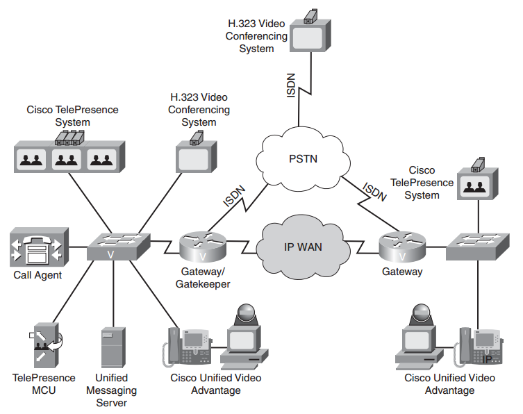 |
| IP-Based Video Network |
Three types of video solutions are shown, as follows:
■ H.323 Video Conferencing System
- Multiple third parties offer H.323 video conferencing systems, which can be used to set up a video conference over an IP or ISDN network.
■ Cisco Unified Video Advantage (CUVA)
- uses a PC, a video camera, and a Cisco IP Phone as a video conferencing station.
- Specifically, the camera connects to a USB port on the PC. Software is loaded on the PC, and the PC is connected to the PC port on a Cisco IP Phone.
- Alternately, the Cisco IP Phone could be the software-based Cisco IP Communicator running on the PC.
- When a voice call is placed between two users running the Cisco Unified Video Advantage product, a video call can automatically be started, with the video appearing on each user’s PC.
■ Cisco TelePresence
- Uses CD-quality audio and High Definition (HD) video (that is, 1080p) displayed on large monitors to create life like video conferences.
Design Considerations for Video
QoS - Like voice, video packets need to be allocated an appropriate amount of bandwidth and be treated with high priority.
QoS CUVA TelePresence Video SurveillanceAvailability - Video networks should be built on an underlying data network with reliable components and redundancy (can approach an uptime of 99.999%)
One-Way Delay max 200 ms max 150 ms max 500 ms
Jitter max 10 ms max 10 ms max 10 ms
Packet Loss max 0.05% max 0.05% max 0.5%
Security - appropriate security measures, such as encryption and authentication, should be in place in a video network.
Multicasting - use of multicasting technologies (allows a multicast server to send traffic to a destination Class D IP address known as a multicast group)
End stations wanting to receive the traffic sent to the multicast group can join the group, thus allowing the multicast server (for example, a video server) to send a single stream of traffic, which is received by multiple recipients wishing to receive the traffic.
Multicasting
Intro: https://www.youtube.com/watch?v=zBiEztnKfyw
Basic Multicast Troubleshooting Tools - http://www.cisco.com/c/en/us/support/docs/ip/ip-multicast/13726-57.html
Consider a video stream that needs to be sent to multiple recipients in a company.
- One approach is to unicast the traffic. The source server sends a copy of every packet to every receiver. Obviously, this approach has serious scalability limitations.
- An alternate approach is to broadcast the video stream, so that the source server only has to send each packet once. However, everyone within a broadcast domain of the network receives the packet, in that scenario, even if they do not want it.
- IP multicast technologies provide the best of both worlds. With IP multicast, the source server only sends one copy of each packet, and packets are only sent to intended recipients.
Multicast roiuting - concerns sending traffic AWAy from the source (as oposite to unicast routing).
Multicast (MC) components:
- MC Source
- MC Routers
- MC Clients
- MC Routing Protocol
- MC Group Management Protocol
! Important !
- In unicast routing, each router examines the destination address of an incoming packet and looks up the destination in a table to determine which interface to use in order for that packet to get closer to its destination. The source address is irrelevant to the router.
- However, in multicast routing, the source address (which is a simple unicast address) is used to determine data stream direction. The source of the multicast traffic is considered upstream. The router determines which downstream interfaces are destinations for this multicast group (the destination address), and sends the packet out through the appropriate interfaces. The term reverse path forwarding is used to describe this concept of routing packets away from the source, rather than towards the destination.
- on the local network, multicast delivery is controlled by IGMP (on IPv4 network) and MLD (on IPv6 network);
- inside a routing domain: PIM or MOSPF are used;
- between routing domains: one uses inter-domain multicast routing protocols, such as MBGP.
- Receivers join a multicast group, denoted by a Class D IP address (that is, in the range 224.0.0.0 through 239.255.255.255).
- The source sends traffic to the Class D address, and through switch and router protocols, packets are forwarded only to intended stations.
- These multicast packets are sent via UDP (that is, best effort).
- When doing a multicast design, also be aware of the potential for duplicate packets being received and the potential for packets arriving out of order.
 |
| IGMP basic architecture |
IGMP - the protocol used between clients (for example, PCs) and routers to let routers know which of their interfaces have multicast receivers attached.

- the router receives this IGMP Join message on its Fast Ethernet 0/0 interface.
- the router knows that when it receives traffic destined for a particular multicast group (as identified in the IGMP Join message), that traffic should be
forwarded out its Fast Ethernet 0/0 interface.
IGMP Versions
IGMP packets are always sent with TTL=1, and are not supposed to be forwarded.
There are three versions of IGMP. However, only two versions are in wide-scale deployment:
■ IGMP Version 1
- When a PC wants to join a multicast group, it sends an IGMP Report message to the router, letting the router know that it wants to receive traffic for a
specific group.
- Every 60 seconds, by default, the router sends an IGMP Query message to determine if the PC still wants to belong to the group.
- There can be up to a three-minute delay before the time the router realizes that the receiver left the group.
- The destination address of this router query is 224.0.0.1, which addresses all IP multicast hosts.
■ IGMP Version 2
- IGMPv2 is similar to IGMP Version 1, except that IGMP Version 2 can send queries to a specific group, and a Leave message is supported.
- a receiver can proactively send a Leave message when it no longer wants to participate in a multicast group, allowing the router to prune its interface earlier.
- IGMP Version 1 and Version 2 hosts and routers do have some interoperability.
- When an IGMPv2 hosts sends an IGMPv2 report to an IGMPv1 router, the IGMP message type appears to be invalid, and it is ignored. Therefore, an IGMPv2 host must send IGMPv1 reports to an IGMPv1 router.
- In an environment with an IGMPv2 router and a mixture of IGMPv1 and IGMPv2 receivers, the version 1 receivers respond normally to IGMPv1 or IGMPv2 queries.
- A version 2 router must ignore any leave message while IGMPv1 receivers are present because if the router processed the IGMPv2 leave message, it would send a group-specific query, which would not be correctly interpreted by an IGMPv1 receiver.
One router must be designated as the querier for that segment.
This IGMP designated querieris the router that has the lowest unicast IP address. To determine which router on a multi-access network is the querier:
Router# show ip igmp interface [interface-id] <--- identifies the IP address of the IGMP querierMulticast on Switches
Router# show ip igmp group <--- displays the IP multicast groups of which a router is aware
- When a Layer 2 switch receives a multicast frame on an interface, by default, the switch floods the frame out all other interfaces.
- To prevent this behavior, the switch needs awareness of what interfaces are connected to receivers for specific multicast groups.
- IGMP snooping - is a feature that can be enabled on many Cisco Catalyst switches, which allows a switch to autonomously determine which interfaces are connected to receivers for specific multicast groups by eavesdropping on the IGMP traffic being exchanged between clients and routers.
Switch(config)# ip igmp snooping <---globally enable IGMP snooping on a Cisco Catalyst switchMulticast Addressing
Switch(config)# ip igmp snooping vlan <vlan_id> <---Once enabled globally, individual VLANs can be enabled or disabled for IGMP snooping
- multicast source sends multicast packets with a Class D destination address.
- The 224.0.0.0 through 239.255.255.255 address range is the Class D address range, because the first four bits in the first octet of a Class D address are 1110.
Some ranges of addresses in the Class D address space are dedicated for special purposes:
Reserved Link Local Addresses:224.0.0.0–224.0.0.255 (Packets will have TTL=1)
- Are used by many network protocols. OSPF uses 224.0.0.5 and 224.0.0.6. RIPv2 uses 224.0.0.9, and EIGRP uses 224.0.0.10.
- Other well-known addresses in this range include 224.0.0.1, which addresses all multicast hosts, and 224.0.0.2, which addresses all multicast routers.
Globally Scoped Addresses:224.0.1.0–238.255.255.255
- Are used for general-purpose multicast applications, and they have the ability to extend beyond the local autonomous system.
Source-Specific Multicast (SSM) Addresses:232.0.0.0–232.255.255.255
- are used in conjunction with IGMPv3, to allow multicast receivers to request not only membership in a group but also to request specific sources from
which to receive traffic.
- multiple sources with different content can all be sending to the same multicast group.
GLOP Addresses:233.0.0.0–233.255.255.255
- provide a globally unique multicast address range, based on autonomous system numbers.
Limited Scope Addresses:239.0.0.0–239.255.255.255
- are used for internal multicast applications (for example, traffic that doesn’t leave an autonomous system), much like the 10.0.0.0/8 address space is a private IP address space
Multicast L2 Addresses
- In addition to Layer 3 addresses, multicast applications must also have Layer 2 addresses (that is, MAC addresses).
- Layer 2 addresses can be constructed directly from the Layer 3 multicast addresses.
- A MAC address is a 48-bit address, and the first half (that is, 24 bits) of a multicast MAC address (in hex) is 01-00-5e.
- The 25th bit is always 0.
- The last 23 bits in the multicast MAC address come directly from the last 23 bits of the multicast IP address.
Consider the following example: multicast IP address of 224.1.10.10, calculate the corresponding multicast MAC address
1234 5678 9012 3456 7890 1234 last 24 bits of MACMulticast RPF
0000.0001.0000.1010.0000.1010 convert the last three octets to binary
0000.0001.0000.1010.0000.1010 if the right-most bit isn’t already 0, it should be changed to a 0, 25th bit of a multicast MAC address is always 0
0 1 -0 a -0 a convert each nibble (each 4-bit section) into its hexadecimal equivalent
01-0a-0a
01-00-5e-01-0a-0a Prepend 01-00-5e to the calculated address to produce the multicast MAC address
- To combat the issue of receiving duplicate packets, Cisco routers perform a Reverse Path Forwarding (RPF) check to determine if a multicast packet is entering a router on the appropriate interface.
- An RPF check examines the source address of an incoming packet and checks it against the router’s unicast routing table to see what interface should be used to get back to the source network.
- If the incoming multicast packet is using that interface, the RPF check passes, and the packet is forwarded.
- If the multicast packet is coming in on a different interface, the RPF check fails, and the packet is discarded.
Distribution Trees
- from source a Tree is created to distribute traffic to all branches
- Only members of a multicast group receive packets destined for that group;
- however, the sender does not need to be a member of the group.
- Multicast traffic flows from a source to a destination over a distribution tree, which is a loop-free path.
The two types of distribution trees are as follows:
Source Distribution Tree
- Creates an optimal path between each source router and each last-hop router (that is, a router connected to a receiver), at the expense of increased memory usage.
- Source distributions trees place (S, G) states in a router’s multicast routing table to indicate the address of the source (S) and the address of the group (G).
Shared Distribution Tree
- Creates a tree from a central rendezvous point(RP) router to all last-hop routers, with source distribution trees being created from all sources to the rendezvous point, at the expense of increased delay.
- Shared distribution trees place (*, G) states in a router’s multicast routing table to indicate that any device could be the source (that is, using the wildcard *character) for the group (G). This (*, G) state is created in routers along the shared tree from the RP to the last-hop routers.
- Because each source for a group does not require its own (S, G), the memory requirement is less for a shared tree compared to a source tree.
PIM-DM Mechanics
- Cisco routers can use the Protocol Independent Multicast(PIM) protocol to construct IP multicast distribution trees.
- PIM’s protocol independence means that it can run over any IP network, regardless of the underlying unicast routing protocol (for example, OSPF or EIGRP).
- The two varieties of PIM are PIM Dense Mode(PIM-DM) and PIM Sparse Mode(PIM-SM).
- PIM-DM uses a source distribution tree, whereas PIM-SM uses a shared distribution tree.
Router(config)# ip multicast-routing <- enabling multicast routing on RouterAfter enabling Multicast, individual interfaces need to be configured for PIM support.
Router(config-if)# ip pim {dense-mode sparse-mode sparse-dense-mode}Cisco recommends sparse-dense-mode, which uses dense-mode to automatically learn the location of an RP, after which the interface runs in sparse-mode.
Show PIM Neighbors
R1# show ip pim neighbor
PIM Neighbor Table
Neighbor Interface Uptime/Expires Ver DR
Address Prio/Mode
10.10.10.1 Ethernet0/0 02:19:41/00:01:38 v2 1 / DR B S
Formation of a PIM Dense Mode distribution tree
1.A multicast source comes up and begins flooding multicast traffic throughout the network.
2.If more than one router is forwarding over a common broadcast medium (ex: Ethernet link), Assert messages are used to determine the PIM forwarder.
The router with the better metric, or (by default) the highest IP address, wins the election.
3.Some routers might not have multicast receivers for the group whose traffic is currently being flooded.
Those routers send a Prune message to their upstream router, requesting that their branch of the distribution tree be pruned off.
However, if there is another router on the same broadcast medium as the router that sent the prune, and if that other router does have IP multicast receivers attached, the prune message is ignored. The reason that the prune message is ignored is because the router that is attached to IP multicast receivers sends a Join Override message.
4.If a receiver comes up on a router that was previously pruned from the tree, that router can rejoin the tree by sending a Graft message.
- A major consideration for PIM-DM, however, is that this flood-and-prunebehavior repeats every three minutes.
- Therefore, PIM-DM does not scale well. A better alternative to PIM-DM is PIM Sparse Mode (PIM-SM).
Formation of a PIM Sparse Mode distribution tree
1.A receiver sends an IGMP Report message to its router indicating that it wants to participate in a particular multicast group.
The receiver’s router (that is, the last-hop router) sends a Join message to the RP, creating (*, G) state along a shared tree between the RP and the last-hop router.
2.A source comes up and creates a source tree between its router (that is, the first-hop router) and the RP. (S, G) state is created in routers along this path.
However, before the source tree is completely established, the source sends its multicast packets to the RP encapsulated inside of unicast Register messages.
3.After the RP receives the first multicast packet over the source tree, it sends a Register Stop message to the source, telling the source to stop sending the multicast
traffic inside of Register messages. Two trees now exist: (1) a source tree from the first-hop router to the RP and (2) a shared tree from the RP to the last-hop router.
However, this might not be the optimal path.
4.The last-hop router discovers from where the multicast traffic is arriving, and the lasthop router sends a Join message directly to the first-hop router to form an optimal path (that is, a source path tree) between the source and the receiver.
5.Because the last-hop router no longer needs multicast traffic from the RP, as it is receiving the multicast traffic directly from the first-hop router, it sends an (S, G) RP-bit Prune message to the RP, requesting the RP to stop sending multicast traffic.
6.With the shared tree to the last-hop router pruned, the RP no longer needs to receive multicast traffic from the first-hop router. So, the RP sends an (S, G) Prune message to the first-hop router. At this point, traffic flows in an optimal path from the firsthop router to the last-hop router. The process of cutting over from the path via the RP to the direct path is called Shortest-Path Tree(SPT) Switchover.
- Comparing PIM-DM versus PIM-SM suggests that PIM-SM offers the benefits of PIM-DM (that is, optimal pathing) without PIM-DM’s flood-and-prune behavior.
You can determine a distribution tree’s topology by examining the multicast routing table of multicast routers in the topology - show ip mroute
Router# show ip mrouteNotice the highlighted (*, G) and (S, G) entries.
IP Multicast Routing Table
Flags: D - Dense, S - Sparse, B - Bidir Group, s - SSM Group, C - Connected,
L - Local, P - Pruned, R - RP-bit set, F - Register flag,
T - SPT-bit set, J - Join SPT, M - MSDP created entry,
X - Proxy Join Timer Running, A - Candidate for MSDP Advertisement,
U - URD, I - Received Source Specific Host Report, Z - Multicast Tunnel,
Y - Joined MDT-data group, y - Sending to MDT-data group
Timers: Uptime/Expires
Interface state: Interface, Next-Hop or VCD, State/Mode
(*, 224.0.100.4), 02:37:12, RP is 192.168.47.14, flags: S
Incoming interface: Serial0, RPF neighbor 10.4.53.4
Outgoing interface list:
Ethernet1, Forward/Sparse, 02:37:12/0:03:42
Ethernet2, Forward/Sparse, 02:52:12/0:01:23
(192.168.46.0/24, 224.0.100.4), 02:37:12, flags: RT
Incoming interface: Ethernet1, RPF neighbor 10.4.53.4
Outgoing interface list:
Ethernet2, Forward/Sparse, 02:44:21/0:01:47
Other valuable information contained in the mroute table includes the incoming interface (IIF), which shows on which interface traffic is entering the router, and the outgoing interface list (OIL), which shows the router interfaces over which the multicast traffic is being forwarded.
Rendezvous Points
- In a PIM-SM network, one or more routers need to be designated as a rendezvous point (RP).
- Non-RPs can be configured to point to a statically defined RP with the global configuration mode command ip pim rp-address <ip-address>
- However, in larger topologies, Cisco recommends that RPs be automatically discovered.
- Cisco routers support two methods for automatically discovering an RP: Auto-RP and Bootstrap Router (BSR).
- Although Auto-RP is a Cisco approach, BSR is a standards-based approach to make the location of RPs known throughout a multicast network.
Common Video Troubleshooting Issues
Bandwidth - sufficient bandwidth should be allocated for supported video applications, you should confirm that the video traffic is not consuming too much bandwidth.
Pervasiveness of Video Applications - The volume of video traffic on a network might be somewhat unpredictable, because users might introduce their own video traffic on a network without the knowledge of network administrators. Therefore, your policy for network use should address the types of traffic a user is allowed to send and receive. Also, you might want to block video from portions of your network.
Security - if a video stream cannot be established, you might check your firewalls and router ACLs to confirm they are not blocking video media (that is, RTP) packets, video maintenance (for example, RTCP) packets, or video-signaling packets (for example, H.323).
QoS - QoS mechanisms should be in place to ensure video packets are sent with priority treatment, and sufficient bandwidth should be allocated for your supported video applications.
Multicast - much of your video troubleshooting might be focused on multicast troubleshooting. For example, confirm that both routers and switches are properly
configured with multicast protocols (for example, PIM-SM on a router and IGMP Snooping on a switch).
Multicast FAQ
http://www.multicasttech.com/?page_id=8
http://web.archive.org/web/20110516204230/http://www.multicasttech.com/faq/
What does (*,G) and (S,G) mean ?
- Any multicast transmission has a Class D multicast group address, G. A multicast group can have more than one source, and each such source will also have a "regular" (Class A, B or C, or CIDR) Internet address, S.
- The notation (*,G) means every possible source for a given group G, while (S,G) means a particular source, at a particular Internet address S, in the group G.
- With IGMP v1 and v2, you join all sources of a group, (*,G), while IGMP v3 will make it possible to join a specific source-group pair, (S,G).
Can multicasting use TCP ?
- No. Multicasting uses UDP (User Datagram Protocol) as its underlying transport protocol.A
- TCP (transmission control protocol) uses frequent transmission of acknowledgement (ACK) packets between the receiver and the transmitter for flow control, and also to determine if packets have arrived safely, in order that dropped packets can be retransmitted. This form of feedback and retransmission does not scale well into the one to many case, although some forms of reliable multicast do use negative acknowledgements (NACKs) to signal the need for retransmission.A
- UDP is a simpler protocol where there is no acknowledgement of the success or failure of the transmission of any packet, and no retransmission, at the transport layer. (In the jargon, UDP is called “best effort.”) Strictly speaking, therefore, multicast data transport is unreliable, and any reliability must be engineered-in at a higher level.
What if my router is not IGMP enabled ?
- Cisco and other vendors support the concept of a stub router, where IGMP packets are passed untouched to a router that does support IGMP, which effectively becomes the first hop router for IGMP traffic from the stub domain. For this to work the stub router must recognize IGMP packets and forward them without decrementing the TTL.
What Multicast Routing Protocols are in Use Today ?
- The protocols for multicast data transport have evolved over the years. The original multicast proposal was for dense mode, where all possible receivers are assumed to want multicast traffic initially and so multicast traffic is flooded throughout the network until receivers specifically request to leave the multicast group and stop receiving the traffic (i.e., are “pruned”). This “flood and prune” technique is relatively straightforward to implement, but is not very efficient as the size of the network increases (it “does not scale,” in the jargon). The first multicast routing protocol in common use,A DVMRPA (for Distance Vector Multicast Routing Protocol), used this technique, and was the protocol of the MBONE for years.
- More recently, a sparse mode protocol has come into common use. In sparse mode, no receiver is assumed to want multicast traffic until it explicitly asks for it. There is thus no unwanted flooding of traffic throughout the network, and so the protocol scales much better and is more usable with large networks.
- The new standard for multicast traffic is Protocol Independent Multicast – Sparse Mode – or PIM-SM. This protocol is called “Protocol Independent” as it uses the unicast routing information to route multicast traffic, regardless of how the unicast routing tables are constructed.
- There is also a PIM Dense Mode(PIM-DM), which combines the simplicity of the old DVMRP with the protocol independence and other improvements in PIM-SM for those situations where a Dense Mode protocol might be appropriate. Another protocol, which mixes the properties of Dense and Sparse Mode, but is only appropriate for domains using the Open Shortest Path First (OSPF) unicast routing protocol, is Multicast – OSPF, or MOSPF.