LFN: BDP > 12.5 KBytes
Sources:
- https://www.cisco.com/c/en/us/td/docs/ios-xml/ios/ipapp/configuration/12-4t/iap-12-4t-book/iap-tcp.html
- https://en.wikipedia.org/wiki/Maximum_segment_size
- http://blog.ine.com/2008/11/05/dealing-with-fragmented-traffic/
- http://routenull.net/route-300-101/
- https://en.wikipedia.org/wiki/IP_fragmentation
IP Fragmentation
IP fragmentation is an Internet Protocol (IP) process that breaks datagrams into smaller pieces (fragments), so that packets may be formed that can pass through a link with a smaller maximum transmission unit (MTU) than the original datagram size. The fragments are reassembled by the receiving host.
RFC 791 describes the procedure for IP fragmentation, and transmission and reassembly of datagrams.RFC 815 describes a simplified reassembly algorithm.
Under IPv4, a router that receives a protocol data unit (PDU) larger than the next hop's MTU has two options:
- drop the PDU and send an Internet Control Message Protocol (ICMP) message which indicates the condition Packet too Big,
- or fragment the IP packet and send it over the link with a smaller MTU.
IPv6 hosts are required to determine the optimal Path MTU before sending packets; however, it is guaranteed that any IPv6 packet smaller than or equal to 1280 bytes must be deliverable.
IPv4 and IPv6 differences
Overall architectural approach to fragmentation, are different between IPv4 and IPv6.
Routers:
- In IPv4, routers perform fragmentation, whereas in IPv6, routers do not fragment, but drop the packets that are larger than their MTU.
- Unlike in IPv4, IPv6 routers never fragment IPv6 packets. Packets exceeding the size of the maximum transmission unit of the destination link are dropped and this condition is signaled by a Packet too Big ICMPv6 type 2 message to the originating node, similarly to the IPv4 method when the Don't Fragment bit is set.
- Though the header formats are different for IPv4 and IPv6, analogous fields are used for fragmentation, so the same algorithm can be reused for IPv4 and IPv6 fragmentation and reassembly.
- When a router receives an IPv4 packet larger than the MTU of the egress interface it splits it into multiple smaller packets. The packets are forwarded as autonomous packets and the destination host is responsible for reassembling them.
- However, when the don’t fragment bit (TCP DF) is set in the header the packets are discarded instead of fragmented. The router will also generate an ICMP Unreachable error message (Type3, Code 4).
Hosts:
- In IPv4, hosts must make a best-effort attempt to reassemble fragmented IP datagrams with a total reassembled size of up to 576 bytes. They may also attempt to reassemble fragmented IP datagrams larger than 576 bytes, but they are also permitted to silently discard such larger datagrams.
- In IPv6, hosts must make a best-effort attempt to reassemble fragmented datagrams with a total reassembled size of up to 1500 bytes, larger than IPv6's minimum MTU of 1280 bytes. Fragmented datagrams with a total reassembled size larger than 1500 bytes may optionally be silently discarded.
Why Fragmentation should be avoided
- Fragmentation isn’t always supported by applications
- CPU and memory overhead to fragment the packets
- CPU and memory overhead to reassemble the packets at the destination
- Entire packets are retransmitted when a single fragment is dropped
- Firewalls using layer 4 to 7 filtering can have issues processing fragments
- impacts applications performance (e.g. TCP needs to re-send the whole packet on a single fragment loss)
- traffic fragmentation is used in numerous network attacks, allowing an attacker to bypass firewalls or IDSes in some situations.
ICMP
- Internet Control Message Protocol
- ICMP for IPv4 is defined in RFC 792
- Is a supporting protocol in the Internet protocol suite.
- It is used by network devices, including routers, to send error messages and operational information indicating, for example, that a requested service is not available or that a host or router could not be reached.
- ICMP is used to obtain diagnostic information (e.g. Round-trip times, routers along a path)
- ICMP differs from transport protocols such as TCP and UDP in that it is not typically used to exchange data between systems, nor is it regularly employed by end-user network applications (with the exception of some diagnostic tools like ping and traceroute).
 |
| ICMP Encapsulation |
ICMP Header differs - https://www.frozentux.net/iptables-tutorial/chunkyhtml/x281.html
 |
| ICMP Header |
Type - The type field contains the ICMP type of the packet. This is always different from ICMP type to type. For example ICMP Destination Unreachable packets will have a type 3 set to it. For a complete listing of the different ICMP types, see the ICMP types appendix. This field contains 8 bits total.
Code - All ICMP types can contain different codes as well. Some types only have a single code, while others have several codes that they can use. For example, the ICMP Destination Unreachable (type 3) can have at least code 0, 1, 2, 3, 4 or 5 set. Each code has a different meaning in that context then. For a complete listing of the different codes, see the ICMP types appendix. This field is 8 bits in length, total. We will discuss the different codes a little bit more in detail for each type later on in this section.
Checksum - The Checksum is a 16 bit field containing a one's complement of the ones complement of the headers starting with the ICMP type and down. While calculating the checksum, the checksum field should be set to zero.
At this point the headers for the different packets start to look different also. We will describe the most common ICMP Types one by one, with a brief discussion of its headers and different codes.
http://telescript.denayer.wenk.be/~hcr/cn/idoceo/ip_icmp.html
| Function | ICMP message(s) | Use |
| Error reporting | Destination Unreachable | a datagram has been discarded due to the reason specified in the message |
| Time exceeded | Time-to-live parameter in a datagram expired and hence discarded. TraceRoute is a tool which maps network routes by sending packets with small TTL values and watching the ICMP timeout announcements. | |
| Parameter Error | A parameter in the header of a datagram is unrecognizable | |
| Reachability testing | Echo request / reply | Checks the reachability of a specified host or gateway. Ping, a common network management tool, is based on this feature. Ping will transmit a series of packets, measuring average round--trip times and computing loss percentages. |
| Congestion control | Source Quench | Requests a host to reduce the rate at which datagrams are sent |
| Route exchange | Redirect | Used by a gateway to inform a host attached to one of its networks to use an alternative gateway on the same network for forwarding datagrams toa specific destination |
| Performance measuring | Time-stamp request / reply | determines the transit delay between two hosts |
| Subnet addressing | Address mask request / reply | Used by a host to determine the address mask associated with a subnet |
The most commonly used messages types are:
Errors:
Destination Unreachable (Type 3)
Redirect (Type 5)
Time Exceeded (Type 11) - TTL expired - used by traceroute
Parameter Problem (Type 12)
Informational:
Echo Reply (Type 0) -ping send
Echo Request (Type 8) - ping reply
Router Advertisement (Type 9)
Router Solicitation (Type 10)
ICMP Redirect
An ICMP redirect is an error message sent by a router to the sender of an IP packet . Redirects are used when a router believes a packet is being routed sub optimally and it would like to inform the sending host that it should forward subsequent packets to that same destination through a different gateway. In theory a host with multiple gateways could have one default route and learn more optimal specific routes over time by way of ICMP redirects.
http://www.cymru.com/gillsr/documents/icmp-redirects-are-bad.htm
IP MTU
https://elifulkerson.com/projects/mturoute.php
mturoute.exe is a small command line application that uses ICMP pings of various sizes in order to determine the MTU values on the path between itself and the target system. It also includes a "traceroute" like mode where it will attempt to determine the lowest MTU between the local host and each hop in the communication.
Maximum Transmission Unit is the size of the largest network layer protocol data unit that can be communicated in a single network transaction.
Ethernet v2 1500
Ethernet jumbo 1501 – 9198 or more
Ethernet IEEE 802.2 LLC 1492
WLAN (802.11) 2304
Token Ring (802.5) 4464 FDDI 4352
Internet IPv4 min 68 - max 64KB
Internet IPv6 min 1280, max of 64KB, but up to 4GB with option
Every internet module must be able to forward a datagram of 68 octets without further fragmentation.
This is because an internet header may be up to 60 octets, and the minimum fragment is 8 octets.
Every internet destination must be able to receive a datagram of 576 octets either in one piece or in fragments to be reassembled.
Fragmentation in IPv4 is handled in either the host or in routers.
https://tools.ietf.org/html/rfc791
MTU vs IP MTU
http://switchpacket.blogspot.md/2014/07/understanding-difference-between-mtu.html
MSS
(The Default) TCP Maximum Segment Size
- The default IP Maximum Datagram Size is 576.
- The default TCP Maximum Segment Size is 536. (TCP MSS = IP Max Datagram-40)
- The maximum size datagram that all hosts are required to accept or reassemble from fragments is 576 octets.
- The maximum size reassembly buffer every host must have is 576 octets.
- Hosts are allowed to accept larger datagrams and assemble fragments into larger datagrams, hosts may have buffers as large as they please.
- Hosts must not send datagrams larger than 576 octets unless they have specific knowledge that the destination host is prepared to accept larger datagrams.
- IPv4 hosts are required to be able to handle an MSS of 536 octets (= 576 - 20 - 20)
- IPv6 hosts are required to be able to handle an MSS of 1220 octets (= 1280 - 40 - 20).
- Small MSS values will reduce or eliminate IP fragmentation, but will result in higher overhead.
- Each direction of data flow can use a different MSS.
- For most computer users, the MSS option is established by the operating system.
PMTUD
Path MTU Discovery is a standardized technique in computer networking for determining the maximum transmission unit (MTU) size on the network path between two Internet Protocol (IP) hosts, usually with the goal of avoiding IP fragmentation.
- PMTUD was originally intended for routers in IPv4.
- However, all modern operating systems use it on endpoints.
- In IPv6, this function has been explicitly delegated to the end points of a communications session.
Many network security devices block all ICMP messages for perceived security benefits, including the errors that are necessary for the proper operation of PMTUD. This can result in connections that complete the TCP three-way handshake correctly, but then hang when data is transferred. This state is referred to as a black hole connection.
A workaround used by some routers is to change the maximum segment size (MSS) of all TCP connections passing through links with MTU lower than the Ethernet default of 1500. This is known as MSS clamping. (because Internet-wide Path MTU Discovery rarely works) link :)
Adjusting the MTU
IP MTU = Adjust the MTU based on the egress interface for packet sending.
IP TCP Adjust-MSS = Adjust the MTU based on the egress interface for packet sending and returning.
Adjusts the MSS value of TCP SYN packets going through a router.
The max-segment-size argument is the maximum segment size, in bytes.
The range is from 500 to 1460.
- Any packet that contains an initial TCP header flowing through your router will be examined against the MSS.
- The MSS in the header will be lowered to this amount if the setting is lower than what is in the header.
- If the header value is already lower, it will flow through unmodified. The end hosts will use the lower setting of the two hosts.
- If this is needing to be tweaked, you would set it at 40 bytes lower than the minimum path mtu. So to account for things like pppoe (1492 byte mtu), I often set the following "ip tcp adjust-mss 1452".
TCP Clamping can be configured so that a router intercepts TCP SYN packets and rewrites the TCP MSS values. As the MSS value doesn’t include headers of the MTU, these need to be taken into account during configuration. This is suitable for VPN tunnels but requires router resources, may not be supported on all routers and affects all TCP traffic.
R1(config)#int fa1/1
R1(config-if)#ip tcp adjust-mss 1360
Setting the DF Bit to Zero
By using a route map a router can set the DF bit to zero and then fragment any packets larger than the egress MTU. However, this also requires router resources and does not work with IPv6 as there is no DF bit to set to zero.
R1(config)#route-map CLEAR-DF permit 10
R1(config-route-map)#set ip df 0
R1(config)#int fa0/0
R1(config-if)#ip policy route-map CLEAR-DF
Time-To-Live (TTL)
IPv4
- The Time to Live (TTL) field is an 8-bit field in the IPv4 header which permits values between 0 and 255.
- A packets TTL value is decremented by 1 every time it passes through a router.
- The purpose of the TTL value is to prevent infinite routing loops as routers will discard packets when their TTL reaches 0.
- When performing a traceroute the sender starts with a TTL of 0 and increments it until finally reaching the destination or the maximum of 255 hops.
- The default TTL value varies by manufacturer, operating system and protocol. For example, the default TTL for Cisco is 254 and a Windows PC is 128. The IANA recommend a default TTL of 64 for the IP protocol.
IPv6 Hop Limit Field
- The IPv6 header contains an 8-bit Hop Limit field which replaces the IPv4 TTL field and performs the same function.
- It is decremented at each router hop until it reaches 0, when it is discarded.
UDP
TCP Starvation/UDP Dominance
- During times of congestion where TCP and UDP flows are in the same QoS class, UDP usually wins the battle for bandwidth.
- This is because TCP includes mechanisms for congestion avoidance, flow control and error discovery. When TCP detects drops it assumes they’re due to network congestion and its back off algorithms reduce the load on the network by throttling traffic.
- Whereas UDP has no flow control, it does not back off during congestion and keeps sending data with no regard to how it affects other traffic flows. Some UDP applications have application-level windowing, flow control, and re-transmission capabilities, but most are oblivious to drops and don’t lower transmission rates.
- TCP Starvation/UDP Dominance is most likely to occur where business critical TCP-based applications are assigned to the same QoS class as UDP-based applications such as video streaming.
Recommendations
- Place critical TCP flows into queues which ensure they always have a good chance of success.
- Isolate TCP and UDP flows by placing them into different queues. However, TCP flows can still experience starvation if its queue reaches the threshold.
It’s important to recognise that WRED (Weighted Random Early Detection) queueing doesn’t help prevent TCP Starvation/UDP Dominance as it only works on TCP flows.
 |
| http://web.opalsoft.net/qos/default.php?p=flows-05 |
TCP
TCP Options Lists - https://www.iana.org/assignments/tcp-parameters/tcp-parameters.xhtml
 |
| TCP Header |
LFN - long fat network
A network with a large bandwidth-delay product is commonly known as a long fat network (shortened to LFN). As defined in RFC 1072, a network is considered an LFN if its bandwidth-delay product is significantly larger than 10^5 bits (12500 bytes).
Ultra-high speed LANs may fall into this category, where protocol tuning is critical for achieving peak throughput, on account of their extremely high bandwidth, even though their delay is not great.
Bandwidth-delay product (BDP) is the maximum amount of data “in-transit” at any point in time, between two endpoints. In other words, it is the amount of data “in flight” needed to saturate the link. You can think the link between two devices as a pipe. The cross section of the pipe represents the bandwidth and the length of the pipe represents the delay (the propagation delay due to the length of the pipe).
Therefore the Volume of the pipe = Bandwidth x Propagation Delay (or Round-Trip-Time).
The volume of the pipe is also the BDP.
BDP = Bandwidth * RTT
57,6 kB - Moderate speed satellite network: 512 kbit/s, 900 ms RTT; B×D = 512×103 b/s × 900×10−3 s = 460,800 bPing measures RTT - the time from client, to server, and back again (rtt - round trip time)
12.5 kB - Residential DSL: 2 Mbit/s, 50 ms RTT, B×D = 2×10⁶ b/s × 50×10−3 s = 100×10^3 b
75 kB - Mobile broadband (HSDPA): 6 Mbit/s, 100 ms RTT, B×D = 6×10⁶ b/s × 10−1 s = 6×10⁵ b
125 kB - Residential ADSL2+: 20 Mbit/s (from DSLAM to residential modem), 50 ms RTT; B×D = 20×10^6 b/s × 50×10−3 s = 125 kB
125 kB - High-speed terrestrial network: 1 Gbit/s, 1 ms RTT; B×D = 10^9 b/s × 10−3 s = 125 kB.
TCP Sliding Window
TCP uses a sliding window for flow control.
The sending device can send all packets within the TCP window size (as specified in the TCP header) without receiving an ACK, and should start a timeout timer for each of them.
The receiving device should acknowledge each packet it received, indicating the sequence number of the last well-received packet.
After receiving the ACK from the receiving device, the sending device slides the window to right side.
- if a window size=0 is reported, the transmitting system must wait for an acknowledgment before sending the next chunk of data.
- if the receiving system reports that the buffer size is larger than the size of a single data packet, the transmitting system knows that it can send multiple chunks of data before waiting for an acknowledgment.
TCP Window Scaling
The TCP Window Scaling feature adds support for the TCP Window Scaling option in RFC 1323.
A larger window size is recommended to improve TCP performance in network paths with large bandwidth, long-delay characteristics that are called Long Fat Networks (LFNs). This TCP Window Scaling enhancement provides that support.
The larger scalable window size will allow TCP to perform better over LFNs.
Use the ip tcp window-size command in global configuration mode to configure the TCP window size.
A TCP sliding window provides more efficient use of network bandwidth because it enables hosts to send multiple bytes or packets before waiting for an acknowledgment.
A window size of zero means "Send no data."
The default TCP window size is 4128 bytes (516 kB).
We recommend you keep the default value unless you know your router is sending large packets (greater than 536 bytes). Use the ip tcp window-size command to change the default window size.
TCP Explicit Congestion Notification
The TCP Explicit Congestion Notification (ECN) feature provides a method for an intermediate router to notify the end hosts of impending network congestion. It also provides enhanced support for TCP sessions associated with applications that are sensitive to delay or packet loss including Telnet, web browsing, and transfer of audio and video data. The benefit of this feature is the reduction of delay and packet loss in data transmissions.
TCP Connection Attempt Time
You can set the amount of time the Cisco IOS software will wait to attempt to establish a TCP connection. Because the connection attempt time is a host parameter, it does not pertain to traffic going through the device, just to traffic originated at the device. To set the TCP connection attempt time, use the ip tcp synwait-time command in global configuration mode. The default is 30 seconds.
TCP Selective Acknowledgment (SACK)
The TCP Selective Acknowledgment feature improves performance in the event that multiple packets are lost from one TCP window of data.
Prior to selective acknowledgment, if TCP lost packets 4 and 7 out of an 8-packet window, TCP would receive acknowledgment of only packets 1, 2, and 3. Packets 4 through 8 would need to be re-sent. With selective acknowledgment, TCP receives acknowledgment of packets 1, 2, 3, 5, 6, and 8. Only packets 4 and 7 must be re-sent.
TCP selective acknowledgment is used only when multiple packets are dropped within one TCP window.
RFC 2018 specified the use of the SACK option for acknowledging out-of-sequence data not covered by TCP's cumulative acknowledgement field.
TCP Time Stamp
The TCP time-stamp option provides improved TCP round-trip time measurements (RTTM). Because the time stamps are always sent and echoed in both directions and the time-stamp value in the header is always changing, TCP header compression will not compress the outgoing packet.
"TCP timestamps are used to provide protection against wrapped sequence numbers. It is possible to calculate system uptime (and boot time) by analyzing TCP timestamps (see below). These calculated uptimes (and boot times) can help in detecting hidden network-enabled operating systems (see TrueCrypt), linking spoofed IP and MAC addresses together, linking IP addresses with Ad-Hoc wireless APs, etc."
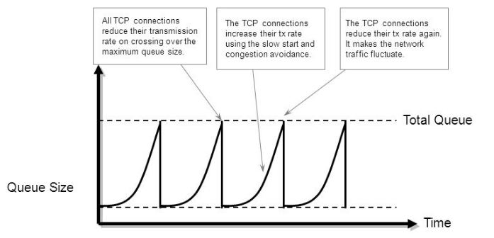
TCP global synchronization
TCP global synchronization in computer networks can happen to TCP/IP flows during periods of congestion because each sender will reduce their transmission rate at the same time when packet loss occurs.
Routers on the Internet normally have packet queues, to allow them to hold packets when the network is busy, rather than discarding them.
Because routers have limited resources, the size of these queues is also limited. The simplest technique to limit queue size is known as tail drop. The queue is allowed to fill to its maximum size, and then any new packets are simply discarded, until there is space in the queue again.
https://en.wikipedia.org/wiki/TCP_global_synchronization
TCP Path MTU Discovery (PMTUD)
Path MTU Discovery is a method for maximizing the use of available bandwidth in the network between the endpoints of a TCP connection, which is described in RFC 1191. IP Path MTU Discovery allows a host to dynamically discover and cope with differences in the maximum allowable maximum transmission unit (MTU) size of the various links along the path. Sometimes a router is unable to forward a datagram because it requires fragmentation (the packet is larger than the MTU you set for the interface with the interface configuration command), but the "don't fragment" (DF) bit is set. The intermediate gateway sends a "Fragmentation needed and DF bit set" Internet Control Message Protocol (ICMP) message to the sending host, alerting it to the problem. Upon receiving this ICMP message, the host reduces its assumed path MTU and consequently sends a smaller packet that will fit the smallest packet size of all the links along the path.
By default, TCP Path MTU Discovery is disabled. Existing connections are not affected when this feature is enabled or disabled.
With RTT-based measurements, it is hard to isolate the direction in which congestion is experienced. One-way measurements solve this problem and make the direction of congestion immediately apparent. Since traffic can be asymmetric at many sites that are primarily producers or consumers of data, this allows for more informative measurements.
UDP dominance can happen during times of congestion. When a link is fully utilized, TCP has automatic congestion avoidance and error discovery methods that allow it to know when to slow down the sending rate. On the contrary, UDP has no such mechanism. It keeps blasting the link with data, with absolutely no regard to how this may affect other traffic flows. Since TCP lowers its transmission rates while UDP continues to utilize the freed bandwidth, this effectively leads to a situation called UDP dominance (or TCP starvation).
One of the best possible ways to prevent this from happening is to classify the TCP and UDP flows into different QoS classes (or at least separating UDP-based, bandwidth-hungry applications into dedicated a dedicated QoS class). Important too is highlighthing the fact that WRED does not help to prevent TCP starvation/UDP dominance as WRED only works on TCP flows, and not on UDP ones.
TCP keepalive
Transmission Control Protocol (TCP) keepalives are an optional feature, and if included must default to off. The keepalive packet contains null data. In an Ethernet network, a keepalive frame length is 60 bytes, while the server response to this, also a null data frame, is 54 bytes. There are three parameters related to keepalive:
- Keepalive time is t he duration between two keepalive transmissions in idle condition. TCP keepalive period is required to be configurable and by default is set to no less than 2 hours.
- Keepalive interval is the duration between two successive keepalive retransmissions, if acknowledgement to the previous keepalive transmission is not received.
- Keepalive retry is the number of retransmissions to be carried out before declaring that remote end is not available.
Keepalive usage:
- Checking for dead peers
- Preventing disconnection due to network inactivity
Out-of-order packet
Out-of-order packet processing can
- significantly degrade system performance,
- reduce TCP session throughput,
- loss of data in some UDP-based protocols (eg: SNA or NetBIOS Fast Sequenced Transport (FST), or Voice-over-IP – VoIP),
- might be even interpreted as attacks by some firewalls.
Out of order packets causes:
- per-packet load balancing with Process Switching (because differential delay may exist within the network), not CEF
- multiple routes to a specific network via multiple routing protocols (multiple paths).
- Queuing mechanisms which don’t forward packets in a first-in/first-out order.
- Asymmetric routing.
Multipath routing is expected to keep packets from the same connection on the same path.
This avoids out-of-order delivery, which can be quite undesirable.
It does so by looking at the address and port of the source and destination
Linux traceroute's default changes the UDP port for each probe, so they change paths.
MTR's default uses ICMP echo, which does not have a port number and therefore its probes will all follow the same path.
>C:\nuttcp\tracetcp.exe facebook.com (TCP)
Tracing route to 185.60.216.35 on port 80
...
5 45 ms 44 ms 45 ms 87.245.232.245 [ae1-5.RT.IRX.FKT.DE.retn.net]
6 46 ms 45 ms 45 ms 157.240.65.66 [ae19.pr01.fra2.tfbnw.net]
7 43 ms 44 ms 43 ms 173.252.66.154 [po111.asw01.fra5.tfbnw.net]
8 43 ms 38 ms 42 ms 157.240.43.3 [po233.psw01.fra5.tfbnw.net]
9 42 ms 43 ms 43 ms 173.252.67.35
10 Destination Reached in 43 ms. Connection established to 185.60.216.35
Trace Complete.
C:\Windows\System32>
mtr --show-ips facebook.com (ICMP)
...
5. ???
6. ???
7. ae29.pr05.fra2.tfbnw.net (103.4.97.60)
8. po115.asw02.fra5.tfbnw.net (204.15.20.164)
9. po242.psw02.fra3.tfbnw.net (31.13.27.221)
10. 157.240.36.17
11. edge-star-mini-shv-02-frt3.facebook.com (157.240.20.35)
mtr --show-ips -u facebook.com (UDP)
...
3. xe-0-2-2.cr1-fra6.ip4.gtt.net (141.136.101.69)
4. xe-0-0-0.cr3-fra2.ip4.gtt.net (141.136.110.117)
xe-4-1-3.cr3-fra2.ip4.gtt.net (141.136.110.113)
xe-4-1-6.cr3-fra2.ip4.gtt.net (141.136.110.105)
xe-0-1-0.cr3-fra2.ip4.gtt.net (141.136.110.125)
xe-0-1-1.cr3-fra2.ip4.gtt.net (141.136.110.129)
xe-4-0-4.cr3-fra2.ip4.gtt.net (141.136.110.109)
xe-0-0-1.cr3-fra2.ip4.gtt.net (141.136.110.121)
xe-9-1-6.cr3-fra2.ip4.gtt.net (89.149.129.57)
5. edgecst-network-gw.ip4.gtt.net (141.136.99.229)
6. po115.asw02.fra5.tfbnw.net (204.15.20.164)
po115.asw01.fra2.tfbnw.net (31.13.24.222)
po115.asw01.fra5.tfbnw.net (31.13.28.168)
7. po231.psw03.fra5.tfbnw.net (157.240.43.5)
po242.psw04.fra5.tfbnw.net (157.240.43.73)
po213.psw04.fra5.tfbnw.net (157.240.43.123)
po211.psw01.fra5.tfbnw.net (157.240.43.101)
po241.psw04.fra5.tfbnw.net (157.240.43.71)
po231.psw04.fra5.tfbnw.net (157.240.43.17)
po213.psw01.fra5.tfbnw.net (157.240.43.105)
po212.psw03.fra5.tfbnw.net (157.240.43.115)
8. 173.252.67.13
173.252.67.109
173.252.67.35
173.252.67.141
173.252.67.99
173.252.67.167
173.252.67.185
173.252.67.3
9. ???