Tunnel-Based Virtual Private Networks
Tunnel is a virtual connection that can physically span multiple router hops.
■ Generic Routing Encapsulation (GRE)
■ Dynamic Multipoint VPN (DMVPN)
■ Multipoint GRE
■ IPsec
GRE tunnel destination - (remote loopback interface IP)
Tunnel Configuration
For the purpose of the example here a Loopback interface will be used as the tunnel source. This Loopback interface will act as the tunnel destination for the tunnel configuration on the remote tunnel device. There are a couple of advantages to using a Loopback interface instead of a physical interface:
• As it is a logical interface it will never go down
• If the tunnel device has multiple uplinks the loopback interface will remain reachable, even if one of these links goes down.
• It allows for a somewhat more generic configuration
Hybrid Virtual Private Networks
Rather than just using a single MPLS-based VPN technology or a single tunnel-based VPN technology, you can use select VPN technologies in tandem.
Example: Layer 3 MPLS VPN set up over a DMVPN.
Overhead
Every time you add an encapsulation, you are adding to the total header size of the packet.
With more headers, the amount of data you can carry inside a single packet is decreased.
As a result, you might have to configure a lower maximum transmission unit (MTU) size for frames on an interface.
GRE - Generic Routing Encapsulation
- GRE tunnel can encapsulate any Layer 3 protocol, which makes it very flexible.
- GRE by itself does not provide any security for the data it transmits
- GRE packet can be sent over an IPsec VPN, causing the GRE packet (and therefore its contents) to be protected.
- GRE tunnel can encapsulate IP multicast packets
Configrutation example:
!ROUTER R1
interface Tunnel1
ip address 192.168.0.1 255.255.255.252
tunnel source Loopback0
tunnel destination 4.4.4.4
!ROUTER R4
interface Tunnel1
ip address 192.168.0.2 255.255.255.252
tunnel source Loopback0
tunnel destination 1.1.1.1
R1# show interfaces tunnel 1
Encapsulation TUNNEL, loopback not set
DMVPN
- Dynamic Multipoint VPN
- allows a VPN tunnel to be dynamically created and torn down between two remote sites on an as-needed basis
- HeadQuarter - role of a Hub, branch routers take the role of Spokes
- hub-and-spoke topology, with the headquarters acting as the hub
- Multipoint GRE, Next Hop Resolution Protocol (NHRP), and IPsec are required to support a DMVPN topology.
 |
| DMVPN example topology |
Multipoint GRE
- allows a router to support multiple GRE tunnels on a single GRE interface.
- Like traditional GRE, mGRE can transport a wide variety of protocols (for example, IP unicast, multicast, and broadcast).
- in a hub-and-spoke topology, a hub router can have a single mGRE interface, and multiple tunnels can use that single interface.
- An interface configured for mGRE is able to dynamically form a GRE tunnel by using Next Hop Resolution Protocol (NHRP) to discover the IP address of the device at the far end of the tunnel.
- traditional GRE (sometimes called point-to-point or p2p GRE)
- traditional GRE use P2P connections with many prefixes /30 (for each P2P connection
- mGRE uses one interface (multipoint) with single /24 prefix (same IP broadcast)
- mGRE tunnel is treated as a non-broadcast multi-access (NBMA)
- mGRE tunnel does not have to be configured with a tunnel destination so we need another protocol to take care of the destination addresses. In this case NHRP is used for NBMA environment.
NHRP
-Next Hop Resolution Protocol (NHRP), defined in RFC 2332, is a Layer 2 address resolution protocol and cache, like Address Resolution Protocol (ARP).
- NHRP is used to map tunnel IP addresses to “physical” or “real” IP addresses, used by endpoint routers.
NHRP Database
Tunnel IP Physical IP
10.0.0.1 192.0.2.1 Spoke-A
10.0.0.2 203.0.113.1 Spoke-B
10.0.0.3 198.51.100.1 Spoke-C
NHRP Registration Process
- When the spokes come online, they each advertise the IP address of their physical interface that is going to be used for tunnel formation,
along with the IP address of the virtual tunnel interface.
- As a result, the Headquarters router populates its NHRP database.
-With the hub’s database populated, a spoke can query the hub to find out the IP address of a physical interface that corresponds to a specific tunnel interface’s IP address.
example:
- Branch C router (10.0.0.3/198.51.100.1) needs to dynamically form a GRE tunnel with the Branch B (10.0.0.2/?phys_IP)
- Branch C router sends an NHRP query to the hub router asking
What physical interface’s IP address is associated with a tunnel interface’s IP address of 10.0.0.2?
- Hub router (that is, the Headquarters router) checks its NHRP database and responds to the query,
telling the Branch C router that the physical interface’s IP address corresponding to the tunnel interface IP address of 10.0.0.2 is 203.0.113.1
- Having dynamically learned the IP address of the physical interface in the Branch B router, the Branch C router sets up a GRE tunnel with the Branch B router
Router# show ip nhrp
192.168.0.2 255.255.255.255, tunnel 100 created 0:00:44 expire 1:59:15
Type: dynamic Flags: authoritative
NBMA address: 10.1111.1111.1111.1111.1111.1111.1111.1111.1111.11
IPsec
- Security in a DMVPN is provided by IPsec
- Confidentiality
- Integrity
- Authentication
- Antireplay
- IPsec uses a collection of protocols to provide its features. One of the primary protocols used by IPsec is the Internet Key Exchange (IKE) protocol.
- There are two phases to establish an IPsec tunnel.
- During IKE Phase 1, a secure Internet Security Association and Key Management Protocol (ISAKMP) session is established.
Also known as an ISAKMP tunnel.
As part of this phase, the IPsec endpoints establish transform sets (that is, a collection of encryption and authentication protocols),
hash methods, and other parameters needed to establish a secure ISAKMP session (sometimes called an ISAKMP tunnel or an IKE Phase 1 tunnel).This collection of parameters is called a security association (SA).
With IKE Phase 1, the SA is bidirectional, meaning that the same key exchange is used for data flowing across the tunnel in either direction.
- IKE Phase 2 occurs within the protection of an IKE Phase 1 tunnel.
Also known as an IPsec tunnel.
A session formed during IKE Phase 2 is sometimes called an IKE Phase 2 tunnel,
or simply an IPsec tunnel. However, unlike IKE Phase 1, IKE Phase 2 performs unidirectional SA negotiations, meaning that each data flow uses a separate key exchange.
- IPsec also relies on either the Authentication Header (AH) protocol (IP protocol number 51) or the Encapsulating Security Payload (ESP) protocol (IP protocol number 50).
Both AH and ESP offer origin authentication and integrity services, which ensure that IPsec peers are who they claim to be and that data was not modified in transit.
- Both AH and ESP can operate in one of two modes, transport mode or tunnel mode.
 |
| IPSec modes |
MPLS - Multiprotocol Label Switching
- Technology commonly used by service providers, although many large enterprises also use MPLS for their backbone network
- MPLS makes forwarding decisions based on labels rather than IP addresses.
- MPLS establishes dedicated path known as LSP (Label Switching Path) before data flow.
(IP routing - Do not establish dedicated path , just transmit data gram which will be routed based on IP addresses.)
- Each MPLS router builds LFIB (Label Forwarding Information Base) table using LDP protocol.
(IP routing - Stores IP routing table)
- 32-bit label is inserted between a frame’s Layer 2 and Layer 3 headers.
- MPLS header is often called a shim header, because it is stuck in between two existing headers.
- MPLS-based VPNs can be grouped into one of two primary categories: Layer 2 MPLS VPNs / Layer 3 MPLS VPNs
- L2 EtherType 0x8847 MPLS unicast
- L2 EtherType 0x8848 MPLS multicast
| MPLS shim header and MPLS stack |
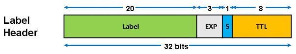 |
| MPLS header fields |
MPLS Header fields:
- 20 bits - Label (the actual label value), A label with the value of 1 represents the router alert label.
- 3bits - Traffic Class
Traffic Class field for QoS (quality of service) priority and ECN (Explicit Congestion Notification). Prior to 2009 this field was called EXP (Experimental)
- 1 bit - S (Bottom of Stack), If this is set, it signifies that the current label is the last in the stack.
- 8 bit - TTL (Time to Live)
MPLS Label Stack
• Usually only one label is assigned to a packet, but multiple labels in a label stack are supported.
• These scenarios may produce more than one label:
– MPLS VPNs (two labels): The top label points to the egress router, and the second label identifies the VPN.
– MPLS TE (two or more labels): The top label points to the endpoint of the traffic engineering tunnel and the second label points to the destination.
– MPLS VPNs combined with MPLS TE (three or more labels).
 |
| MPLS Label Stack |
• The outer label is used for switching the packet in the MPLS network (points to the TE destination).
• Inner labels are used to separate packets at egress points (points to egress router and identifies VPN).
Top = Outer = LSP label (per TDP, LDP or RSVP)
Bottom = Inner = VPN label (per MP-BGP)
BGP
MPLS provider edge (PE) router is also known as an Edge Label Switch Router [ELSR]
MPLS customer edge (CE) router
The normal version of BGP (Border Gateway Protocol) only supported IPv4 unicast prefixes.
Nowadays we use MP-BGP (Multiprotocol BGP) which supports different addresses:
IPv4 unicast
IPv4 multicast
IPv6 unicast
IPv6 multicast
MP-BGP - multiprotocol BGP, in MPLS used to exchange the VPN labels
Layer 2 MPLS VPN - as a logical Layer 2 switch
Layer 3 MPLS VPN - SP PE router establishes a peering relationship with a CE router
sources:
http://blog.globalknowledge.com/2010/06/16/mpls-part-10/