Recommended Configuration Maximums NSX for vSphere 6.3 - Update 1 - Last Updated 7 Nov, 2017
From NSX Reference Design v.30
https://www.vmware.com/content/dam/digitalmarketing/vmware/en/pdf/products/nsx/vmw-nsx-network-virtualization-design-guide.pdf
Terminology
SDDC - Software Defined Data Center
North-South traffic - external physical network
East-West traffic - inside a SDDC
BUM - Broadcast, Unknown Unicast, Multicast
East-West traffic - inside a SDDC
Hair Pinning the traffic - the traffic goes out the ESXi host across the network to end up at the same ESXi host.
Leverage - use (something) to maximum advantage.
Tenant is a customer or an organization such as Palo Alto Networks.
A sub-tenant is a department or business unit within the organization such as Marketing, Accounting, HR
LIF - Logical Interfaces
Leverage - use (something) to maximum advantage.
Tenant is a customer or an organization such as Palo Alto Networks.
A sub-tenant is a department or business unit within the organization such as Marketing, Accounting, HR
LIF - Logical Interfaces
BUM - Broadcast, Unknown Unicast, Multicast
Control Plane represented by a virtual machine called Logical Router (LR) Control VM.
Dynamic routing protocols such as OSPF, BGP, IS-IS run between the Control VM and the upper layer, on NSX represented by the NSX Edge Gateway.
===NSX for vSphere (NSX-v) components:
-vSphere ESXi – server hypervisor.
-vSphere Distributed Switch – the advanced Layer 2 virtual Switch that VMware provides with the Enterprise Plus licence (you cannot use the vSphere Standard Switch with NSX).
-NSX Manager – management interface of NSX, presented via the vSphere Web Client and has a northbound NSX API.
-NSX Controller – the control plane of NSX which also has a northbound NSX API.
-Logical Switch – VXLAN tunnels that run across disparate networks.
-Edge Services Gateway (ESG) – provides L3-L7 network services to the outside world.
-Distributed Logical Router (DLR) – provides L3-L7 network services to the physical and virtual infrastructure via a hypervisor service for the data plane and a virtual appliance for the control plane.
-Distributed Firewall – this is a service that runs on ESXi and provides micro-segmentation of virtual infrastructure
-Third Party integrations – advanced L3-L7 services provided by Third Parties via the NSX API. eg. Palo Alto Networks, McAfee, Trend Micro, F5, Citrix, Silver Peak, etc.
-Physical Network – traditional core, aggregate, distribution, access or Clos-type Leaf & Spine architectures
-Virtual overlay to Physical network gateways – the NSX virtual overlay integrates with the physical world via a gateway. eg. Routing, L2 Extension, VXLAN, etc.
North-South traffic:
The ESG (aka ESR) is a router in a VM (it also does other L4-L7 services like FW, LB, NAT, VPN, if you want). Both the control and data plane of the ESR router are in the VM. This VM establishes routing protocol sessions with other routers and all of the traffic flows through this VM. It’s like a router, but in a VM. This should be straight forward, not requiring much explanation.
Layer 4 firewall and load balancer operations can reach and exceed 10 Gbps throughput, with high connections per second (cps). Layer 7 operations also perform well compared to hardware counterparts.
East-West traffic:
DLR the data plane is distributed in kernel modules at each vSphere host, while only the control plane exists in a VM. And that control plane VM also relies on the NSX controller cluster to push routing updates to the kernel modules.
The DLR is unique because it enables each vSphere hypervisor host to perform L3 routing between virtual and physical subnets in the kernel at line rate.
The ESR and DLR are independent. You can deploy both in the same virtual network, just one, or none.
The IP address and MAC address on LIF1 is the same on all vSphere hosts (vMAC).
LIFs attached to physical VLAN subnets will have unique MAC addresses per vSphere host.
Designated Instance (DI) for LIF3 is only needed for LIFs attached to physical VLANs. There is only one DI per LIF. The DI is responsible for ARP resolution.
http://bradhedlund.com/2013/11/20/distributed-virtual-and-physical-routing-in-vmware-nsx-for-vsphere/
===What are L2 to L7 services?
VLAN, VXLAN tunnels, Network Firewall, IPS, Application Firewall,
NAT, Routing (OSPF, BGP, IS-IS), Load Balancing,
SSL VPN, IPSec VPN, Route redistribution, etc.
NSX components
VMware NSX for vSphere - Network Virtualization and Security Platform for the software-defined data center that emerged from VMware after they acquired Nicira.
An NSX deployment consists of a data plane, control plane, and management plane.
 |
| NSX Components |
Data Plane
The NSX data plane is implemented by the NSX vSwitch (which is based on the VDS with additional components added to enable rich services).
The add-on NSX components include kernel modules distributed as VMware installation bundles (VIBs).
These modules run within the hypervisor kernel, providing services including distributed routing, distributed firewall, and VXLAN to VLAN bridging
Logical Networking Components
* switching
* ECMP
* DLR - distributed logical routing (DLR) provides an optimal data path for traffic within the virtual infrastructure
* P<->V - connectivity to physical networks
NSX Services Platform
Networking and Edge Services:
Edge Firewall - are part of the NSX Edge Services Gateway (ESG)
VPN: L2 VPN, IPSEC VPN, and SSL VPN services to enable L2 and L3 VPN services.
Logical Load-balancing: L4-L7 load balancing with support for SSL termination.
DHCP & NAT Services: Support for DHCP servers and DHCP forwarding mechanisms; NAT services.
Security Services and Distributed Firewall
Distributed Firewall – Security enforcement is done directly at the kernel and vNIC level.
NSX also provides an extensible framework, allowing security vendors to provide
an umbrella of security services. Popular offerings include anti-virus/anti-
malware/anti-bot solutions, L7 firewalling, IPS/IDS (host and network based)
services, file integrity monitoring, and vulnerability management of guest VMs.
Edge services and security services can be provided by either built-in components of NSX Manager or by integrated 3rd party vendors.
 |
| NSX install order |
Control Plane
*NSX controller -enables multicast free VXLAN and control plane programming of elements such as the Distributed Logical Routing (DLR).
NSX controller nodes are deployed in a cluster of odd number instances.
Responsible for managing the hypervisor switching and routing modules.
The NSX controller supports an ARP suppression mechanism, reducing the need to flood ARP broadcast requests across an L2 network domain where virtual machines are connected.
It is critical to understand that data plane traffic never traverses the control plane component.
For resiliency and performance, production deployments of controller VM should be in three distinct hosts.
In order to increase the scalability characteristics of the NSX architecture,
a slicing mechanism is utilized to ensure that all the controller nodes can be active at any given time.
Each node in the controller cluster is identified by a unique IP address.
When an ESXi host establishes a control-plane connection with one member of the cluster, a full list of IP addresses for the other members is passed down to the host.
In the case of failure of a controller node, the slices owned by that node are reassigned to the remaining members of the cluster.
The master is responsible for allocating slices to individual controller nodes, determining when a node has failed, and reallocating the slices to the other nodes.
The election of the master for each role requires a majority vote of all active and inactive nodes in the cluster.
Management Plane
NSX manager is the management plane for the NSX eco-system.
NSX manager provides configuration and orchestration of:
• Logical networking components – logical switching and routing
• Networking and Edge services
• Security services and distributed firewall
SSL is disabled by default in NSX software release 6.0 (confidentiality of the control plane communication)
An NSX manager outage may affect only specific functionalities such as identity
based firewall or flow monitoring collection.
* NSX manager data (e.g., system configuration, events, audit log tables) can be backed up at any time by performing an on-demand backup from the NSX Manager GUI
Restoring a backup is only possible on a freshly deployed NSX manager appliance that can access one of the previously backed up instances.
NSX manager typically resides in the same subnet (VLAN) as vCenter and communicates over the management network. This is not a strict requirement;
NSX provides new functionalities by installing three VIBs modules at the kernel level so that they hypervisor is capable of the following:
- VXLAN encapsulation
- Distributed logical routing
- Distributed logical firewalling
VXLAN
Virtual Extensible LAN (VXLAN) has become the “de-facto” standard overlay technology and is embraced by multiple vendors;
VMware in conjunction with Arista, Broadcom, Cisco, Citrix, Red Hat, and others developed it.

- VXLAN is a L2 over L3 (L2oL3) encapsulation technology.
The original Ethernet frame generated by a workload is encapsulated with external VXLAN, UDP, IP and Ethernet headers to ensure it can be transported across the network infrastructure interconnecting the VXLAN endpoints (e.g., ESXi hosts).
- Scaling beyond the 4094 VLAN limitation on traditional switches has been solved by leveraging a 24-bit identifier, named VXLAN Network Identifier (VNI),
which is associated to each L2 segment created in logical space.
This value is carried inside the VXLAN Header and is normally associated to an IP subnet, similarly to what traditionally happens with VLANs.
* Note – The terms “VXLAN segment”, “Virtual Network” (VN) and “Logical Switch” (LS) all refer
to the logical layer 2 domain created in the logical network space and will be used interchangeably in this document.
- NSX uses 8472 as destination port value for the external UDP header.
- Hashing of the L2/L3/L4 headers present in the original Ethernet frame is performed to derive the source port value for the external UDP header.
This is important to ensure load balancing of VXLAN traffic across equal cost paths available inside the transport network infrastructure.
- The source and destination IP addresses used in the external IP header uniquely identify the ESXi hosts originating and terminating the VXLAN
encapsulation of frames. Those are usually referred to as VXLAN Tunnel Endpoints (VTEPs).
- Encapsulating the original Ethernet frame into a UDP packet increases the size of the IP packet. For this reason, increasing the MTU to a minimum of
1600 bytes is recommended for all interfaces in the physical infrastructure that will carry the frame.
Transport Zone - defines a collection of ESXi hosts that can communicate with each other across a physical network infrastructure.
This communication happens over one or more interfaces defined as VXLAN Tunnel Endpoints (VTEPs).
A Transport Zone extends across one or more ESXi clusters and commonly defines a span of logical switches.
A VDS may span multiple ESXi hosts.
A Logical Switch can extend across multiple VDS.
VXLAN configuration can be broken down into three important steps:
- Configure Virtual Tunnel Endpoint (VTEP) on each host.
- Configure Segment ID range to create a pool of logical networks. (In some configurations, this step may require Multicast group address configuration.) However, in this lab we are utilizing Unicast mode and we don't need to specify a multicast range.
- Define the span of the logical network by configuring the transport zone.
DFW - firewall
NSX Distributed Firewall (DFW) - provides L2-L4 stateful firewall services to any workload in the NSX environment.
By default, NSX Manager, NSX Controllers, and Edge services gateways are automatically __excluded__ from DFW function.
One DFW instance is created per VM vNIC; for example, if a new VM with 3 vNICs is created, 3 instances of DFW will be allocated to this VM.
DFW policy rules can be written in 2 ways, using L2 rules (Ethernet) or L3/L4 rules.
It is important to remember that L2 rules are always enforced before L3/L4 rules.
With NSX release 6.2, VMtools installed in VM is not mandatory.
The DFW function is activated when a host is prepared for enforcement.
During this operation, a kernel VIB is loaded into the hypervisor.
This VIB is known as the VMware Internetworking Service Insertion Platform (VSIP).
A set of daemons called vsfwd runs permanently on the ESXi host and performs the following tasks:
- Interact with NSX Manager to retrieve DFW policy rules.
- Gather DFW statistics information and send them to the NSX manager.
- Send audit logs information to the NSX manager.
This service insertion platform adds complementary services like SpoofGuard and traffic redirection from third party partners including Palo Alto Networks, CheckPoint, Fortinet, Intel Security, Symantec, RAPID7, and Tend Micro).
The communication path between the vCenter Server and the ESXi host uses the vpxa process on the ESXi host.
This is only used for vSphere related purposes, including VM creation, storage modification, and NSX manager IP address distribution.

SpoofGuard protects against IP spoofing by maintaining a reference table of VM name and IP address, populating it with information retrieved from VMtools during VM’s initial boot up.
SpoofGuard is inactive by default and must be explicitly enabled per Logical Switch or VDS port-group. When a VM IP address change is detected, traffic from/to this VM can be blocked by the DFW until an NSX administrator approves this new IP address.
Traffic redirection is defined under Service Composer/Security Policy for NSX version 6.0 or under Partner Security Services tab of the DFW menu in NSX version 6.1.
The DFW instance on an ESXi host contains 2 separate tables.
The rule table is used to store all policy rules, while the connection tracker table caches flow entries for rules with permit actions.
A specific flow is identified by the 5-tuple information consisting source IP address, destination IP address, protocols, L4 source port, and L4 destination port fields.
By default, DFW does not perform a lookup on L4 source port, but it can be configured to do so by defining a specific policy rule.
The DFW default policy rule, located at the bottom of the rule table, is a “catch-all” rule; packets not matching any other rules will be enforced by the default rule.
After the host preparation operation, the DFW default rule is set to ‘allow’ action.
Logical Switch
Logical Switching is defined by a segment ID (VXLAN ID) and is unique per NSX manager. Starting with the NSX 6.2 release, segment ID range planning is
required in order to enable cross-VC connectivity.
It is recommended to keep the segment ID unique for each NSX domain to leverage cross-VC capabilities in NSX 6.2 release; this will help avoid the requirement of renumbering of segment IDs.
Multi-destination traffic types are collectively referred to using the acronym BUM (Broadcast, Unknown Unicast, Multicast).
NSX supports three different replications modes to enable multi-destination communication on VXLAN backed Logical Switches: multicast, unicast and hybrid.
By default, a Logical Switch inherits its replication mode from the Transport Zone, though this behavior can be overridden at the Logical Switch level.
Multicast Mode
is the process for handling BUM traffic specified by the VXLAN IETF draft, and does not leverage any of the enhancements brought by NSX with the introduction of the controller clusters.
A multicast IP address must be associated to each defined VXLAN L2 segment (i.e., Logical Switch). L2 multicast capability is used to replicate traffic to all VTEPs in the local segment.
Additionally, IGMP snooping should be configured on the physical switches to optimize the delivery of L2 multicast traffic.
To ensure multicast traffic is also delivered to VTEPs in a different subnet from the source VTEP, the network administrator must configure PIM and enable L3 multicast routing.
 |
| VXLAN segment 5001 is associated with multicast group 239.1.1.1 |
When the first VM is connected to the logical switch, the ESXi hypervisor hosting the VM generates an IGMP join message to notify the physical infrastructure that it is interested in receiving multicast traffic sent to that specific group.
As a result of the IGMP joins sent by ESXi1-ESXi-3, multicast state is stored in the physical network to ensure delivery of multicast frames sent to the 239.1.1.1 destination.
When configuring multicast mode, consideration must be given on how to perform the mapping between VXLAN segments and multicast groups.
- The first option is to perform a 1:1 mapping.
- The other choice involves leveraging a single multicast group for all the defined VXLAN segments.
Unicast Mode
Unicast mode represents the opposite approach from multicast mode, wherein the decoupling of logical and physical networks is fully achieved. In unicast mode, the ESXi hosts in the NSX domain are divided in separate groups (i.e., VTEP segments) based on the IP subnet of VTEP interfaces. An ESXi host in each VTEP segment is selected to play the role of Unicast Tunnel End Point (UTEP).
Traffic will only be sent by the source ESXi to the remote UTEPs if there is at least one active VM connected to an ESXi host in that remote segment.
Hybrid mode offers operational simplicity similar to unicast mode – IP multicast routing configuration is not required in the physical network – while leveraging the L2 multicast capability of physical switches.
Hybrid mode allows deployment of NSX in large L2 topologies by helping scale multicast at layer 2 with the simplicity of unicast.
Populating the Controller Tables
Controller tables handle information essential for L2 unicast communication.
Control plane communication between ESXi hosts and the controller cluster is used to populate the VTEP, MAC, and ARP tables on controller nodes.
VNI-VTEP Report
1) The ESXi host generates a control plane message to the specific controller node in charge of that specific logical switch slice with VNI/VTEP mapping information.
2) The controller node populates its local VTEP table with this information and sends a report message to all ESXi hypervisors hosting VMs actively connected to that same VXLAN segment.
3) The ESXi hosts can then populate their local VTEP tables, and this information can be leveraged to determine the list of VTEPs for multi-destination traffic replication.
MAC Report
ESXi hosts also report the MAC address for VMs locally connected to a specific VNI. The controller uses those reports to populate its local MAC table, but unlike the VNI-VTEP report, it does not send this information to all the ESXi hosts. Because of this, ESXi hosts only aware of the locally onnected MAC addresses,
ARP Report
The final piece of information shared with the controller is the IP address of the VMs. This controller populates its local ARP table in order to perform the ARP suppression functionality discussed the “Unicast Traffic (Virtual to Virtual Communication)” section.
The ESXi hosts learn the IP address of locally connected VMs in two ways.
- For VMs obtaining an IP address using DHCP, the ESXi host will snoop the DHCP response sent by the DHCP server.
- For VMs that are statically addressed, ARP requests originated by the VMs will be used to learn their IP addresses. Once the IP address of the machine is learned, the ESXi hosts send the MAC/IP/VNI information to the controller to populate its local ARP table.
Unicast Traffic (Virtual to Virtual Communication) - ARP Resolution via NSX Controller
Using the information from its tables, the NSX controller can perform an “ARP suppression” that avoids the need to flood ARP traffic in the L2 domain (i.e., VXLAN segment) where the virtual machines are connected. ARP requests represent the vast majority of L2 broadcast traffic found in the network, so removing these provides significant benefits to the stability and scalability of the overall network infrastructure.
Unicast Traffic (Virtual to Physical Communication)
NSX offers this functionality in software through the deployment of NSX L2 bridging, allowing VMs to be connected at layer 2 to a physical network through VXLAN to VLAN ID mapping. This is supported even where the hypervisor running the VM is not physically connected to that L2 physical network.
The VXLAN-VLAN bridging configuration is part of the distributed router configuration; it is running on the same ESXi host where the control VM is located.
- The VXLAN-VLAN mapping is always performed in a only 1:1 fashion.
- A given bridge instance for a specific VXLAN-VLAN pair is always active on a single ESXi host.
- Through configuration it is possible to create multiple bridges instances for different VXLAN-VLAN pairs and ensure they are spread across separate ESXi hosts. This improves the overall scalability of the L2 bridging function.
- The NSX layer 2 bridging data path is entirely performed in the ESXi kernel rather than in user space.
- Similar to Edge VM, the control VM runs in active-standby mode. In case of the active control VM failure, the convergence of bridged traffic is governed by hear-beat timer (15 seconds by default) between active-standby.
Logical Routing
The logical routing capability in the NSX platform provides the ability to interconnect both virtual and physical endpoints deployed in different logical L2 networks.
The deployment of logical routing can serve two purposes; interconnecting endpoints – logical or physical – belonging to separate logical L2 domains or interconnecting endpoints belonging to logical L2 domains with devices deployed in the external L3 physical infrastructure.
DLR
Distributed routing is provided by a logical element called Distributed Logical Router (DLR).
The DLR is essentially a router with directly connected interfaces to all hosts where VM connectivity is required.
The supervisory function (i.e., control plane) to control the forwarding is imported from a control VM.
The DLR consists of two primary components:
- Control Plane: The control plane is provided by the DLR Control VM and NSX controller.
The control plane supports dynamic routing protocols (e.g., BGP, OSPF), exchanges routing updates with the next layer 3 hop device (e.g., NSX Edge), and communicates with the NSX manager and
the controller cluster. High availability for the DLR control VM is supported through an active/standby configuration.
- Data Plane: DLR kernel modules (e.g., VIBs) are installed on the ESXi hosts part of the NSX domain. The traditional data plane functionality of route and ARP lookups is performed by the kernel modules. The kernel modules are equipped with logical interfaces (LIFs) connecting to the different logical switches.
Each LIF has an IP address representing the default IP gateway for its logical L2 segment as well as a vMAC address. The IP address is unique per LIF and remains same where the logical switch exists. The vMAC associated with each LIF remains the consistent in each hypervisor as well and thus during the vMotion, the default gateway and MAC remains the same.
 |
| Logical Routing Components |
LR Control VM
Control plane- doesn’t perform any routing so if it dies virtual machines traffic keeps going. Routes learnt are pushed to the hypervisor in a process that can be summarised as follow:
- NSX Edge Gateway (EGW) learns a new route from the “external world”
- LR Control VM learns this route because it’s a “neighbor” (adjacency) talking to EGW via the Protocol Address
- LR Control VM pass the new route to the NSX Controller(s)
- NSX Controller pushes (in a secure manner) the new route to the ESXi hosts via User World Agent (UWA) and the route gets installed on every host
Logical Interfaces (LIFs)
- Internal LIFs which act as default gateway for each logical switch (web, app, db)
- Uplink LIF connects the “northbound world” for north-south traffic.
- Internal LIFs which act as default gateway for each logical switch (web, app, db)
- Uplink LIF connects the “northbound world” for north-south traffic.
DLR components:
– Data plane - resides in the kernel of the ESXi hosts participating in a given NSX Transport Zone. It uses the NSX VIB software packages as agents. (P.S. : A "Transport Zone" determines on which ESXi clusters Logical Switches and DLRs will span across)
– Control Plane : Every time you deploy a Distributed Router, it also deploys a "Control VM", this VM is the control plane for the DLR. You can access it from SSH, or from the VM's console. But most of the time you won't need to do this unless you're troubleshooting an issue.
– Management Plane : The management plane for Distributed Logical Routers is, like every other NSX component, part of the vSphere Web Client. You'll find everything you need to configure and manage your Distributed Router Instances under the NSX Edges tab.
Maximum numbers tenants that can be connected to the same NSX Edge to nine (a VM 10 vmnic - 1 at least uplink).
Logical Firewalling and Security Services
The VMware NSX platform includes two firewall components:
- a centralized firewall service offered by the NSX ESG;
- a Distributed Firewall (DFW) enabled in the kernel as a VIB package on all the ESXi hosts part of a given NSX domain. The DFW provides firewalling with near line rate performance, virtualization, identity awareness, activity monitoring, and other network security features native to network virtualization
Network Isolation
VXLAN - virtual networks are isolated from any other virtual networks as well as from the underlying physical infrastructure by default, delivering the security principle of least privilege. Virtual networks are created in isolation and remain isolated unless explicitly connected together.
Virtual networks are also isolated from the underlying physical network.
Network Segmentation
Network segmentation, like isolation, is a core capability of VMware NSX network virtualization.
Between the guest VM and logical network (e.g., Logical Switch or DVS portgroup VLAN-backed), there is a service space implemented into the vNIC context. Slot-ID materializes service connectivity to the VM.
Slot 2 is allocated to DFW, slot 4 to the specific third party advanced security services. Additional slots are available to plug in additional third-party services.
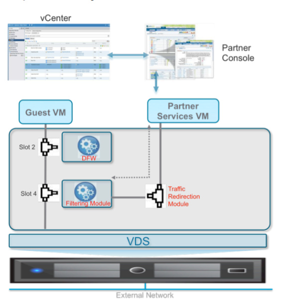
Traffic exiting the guest VM always follows the path with increasing slot-ID number, so a packet would first be redirected to slot 2 and then slot 4.
Traffic reaching the guest VM follows the path in the reverse slot-ID order; first slot 4 and then slot 2.
– Control Plane : Every time you deploy a Distributed Router, it also deploys a "Control VM", this VM is the control plane for the DLR. You can access it from SSH, or from the VM's console. But most of the time you won't need to do this unless you're troubleshooting an issue.
– Management Plane : The management plane for Distributed Logical Routers is, like every other NSX component, part of the vSphere Web Client. You'll find everything you need to configure and manage your Distributed Router Instances under the NSX Edges tab.
Maximum numbers tenants that can be connected to the same NSX Edge to nine (a VM 10 vmnic - 1 at least uplink).
NSX software release 6.1 allows for scaling up the number of tenants supported by a single NSX Edge services gateway with the introduction of the ESG trunk interface.
The definition of an ESG vNIC interface as trunk allows the connection of multiple DLR instances to that single vNIC, leveraging the sub-interface construct traditionally available on physical networking devices.
As of release 6.1.2, 200 sub-interfaces (i.e. tenants) are supported on a single ESG instance across all the available vNIC interfaces deployed as trunks.
Routing peering can be established on each trunk sub-interface.
- a centralized firewall service offered by the NSX ESG;
- a Distributed Firewall (DFW) enabled in the kernel as a VIB package on all the ESXi hosts part of a given NSX domain. The DFW provides firewalling with near line rate performance, virtualization, identity awareness, activity monitoring, and other network security features native to network virtualization
Network Isolation
VXLAN - virtual networks are isolated from any other virtual networks as well as from the underlying physical infrastructure by default, delivering the security principle of least privilege. Virtual networks are created in isolation and remain isolated unless explicitly connected together.
Virtual networks are also isolated from the underlying physical network.
Network Segmentation
Network segmentation, like isolation, is a core capability of VMware NSX network virtualization.
Between the guest VM and logical network (e.g., Logical Switch or DVS portgroup VLAN-backed), there is a service space implemented into the vNIC context. Slot-ID materializes service connectivity to the VM.
Slot 2 is allocated to DFW, slot 4 to the specific third party advanced security services. Additional slots are available to plug in additional third-party services.
Traffic exiting the guest VM always follows the path with increasing slot-ID number, so a packet would first be redirected to slot 2 and then slot 4.
Traffic reaching the guest VM follows the path in the reverse slot-ID order; first slot 4 and then slot 2.
Introduction to Service Composer
NSX introduces a mechanism for deploying security services independent of the underlying topology. Traditional services like firewall or advanced services like agentless AV, L7 firewall, IPS, and traffic monitoring can be deployed independent of the underlying physical or logical networking topologies.
NSX provides a framework called Service Composer to enable deployment of security services for the datacenter.
Service Composer contains three broad parts:
- Intelligent Grouping via Security Groups: NSX achieves decoupling of workloads from the underlying topology via creation of these security groups.
- 3rd Party Service Registration and Deployment: Enables 3rd party vendor registration with NSX and deployment of vendor security technologies throughout the datacenter
- Security Policies: A security policy allows flexibility in applying specific security rules to specified workloads. Policies include governance of not just the built-in NSX security services, but also redirection to third party services like Palo Alto Networks, CheckPoint and Fortinet once the 3rd party service is registered with NSX.
Introduction to Intelligent Grouping
NSX provides grouping mechanism criteria can include any of the following:
- vCenter Objects: VMs, Distributed Switches, Clusters, etc.
- VM Properties: vNICs, VM names, VM operating Systems, etc.
- NSX Objects: Logical Switches, Security Tags, Logical Routers, etc.
Grouping mechanisms can be either static or dynamic in nature, and a group can be any combination of objects.
Grouping criteria can include any combination of vCenter objects, NSX Objects, VM Properties, or Identity Manager objects.
A security group in NSX is based on all static and dynamic criteria along with static exclusion criteria defined by a user.
 |
| Security of Group Attributes |
Combining different objects for the grouping criteria results in the creation of the “AND” expression in the NSX system.
Dynamic grouping mechanisms are more flexible and are characterized by allowing expressions that evaluates to defining the virtual machines for a group. The core difference is the ability to define “AND/OR” as well as “ANY/ALL” criteria for the grouping.
Intelligent Grouping – An Example of Efficiency