- CoS is a 3-bit (CS0 through CS7) field that is present in an Ethernet frame header when 802.1Q VLAN tagging is present. Layer2 only
- DSCP (Differentiated Services Code Point) - modern QoS in IP header. Layer 3 QoS
- TOS (Type of service) - deprecated mechanism used with IP header for QoS,
- Re-marking of traffic is typically necessary. For example, re-marking CoS values to IP Precedent or DSCP values.
| Field Name | Header(s) | Length (bits) | Where Used |
| DSCP | IPv4, IPv6 | 6 | End-to-end packet |
| IPP | IPv4, IPv6 | 3 | End-to-end packet |
| CoS | 802.1Q, 802.1p | 3 | Over VLAN trunk |
| TID | 802.11 | 3 | Over Wi-Fi |
| EXP | MPLS Label | 3 | Over MPLS WAN |
TID: Wi-Fi Traffic Identifier
COS: Class of Service
EXP: Experimental
IPP: IP Precedence
DSCP: Differentiated Services Code Point
QoS terminology
 |
| Cisco QoS Model |
- Layer-2 perspective (CoS),
- Layer-3 (IP Precedence, DSCP)
- higher (NBAR)
- PBR, Policy-Based Routing
- CAR, Committed Access Rate
- Class-Based Packet Marking
Queuing (congestion management)
- FIFO, First-In-First-Out
- PQ, Priority queueing - strict
- WRR, Weighted Round robin:
- FQ, Fair queueing
- CQ, Custom queueing
- DRR, deficit Round Robin - in hardware
- WFQ, Weighted fair queueing:
--Flow-based WFQ (WFQ)
--DWFQ, Distributed WFQ
--CBWFQ, Class-based WFQ
--DCBWFQ, Distributed class-based WFQ
- LLQ, Low Latency Queueing - strict PQ to CBWFQ
- LLQ, Distributed LLQ, and LLQ for Frame Relay
- IP RTP Priority and Frame Relay IP RTP Priority
Congestion Avoidance
- ingress interface queue, forward engine or egress queue
- WTD, Weighted Tail Drop
- RED, Random Early Detection
- WRED, Weighted Random Early Discard
- DWRED - Cisco high-speed version of WRED
- CBWRED, Class-Based Weighted Random Early Detection
- Flow-Based WRED
- DiffServ Compliant WRED
- DBL, Dynamic Buffir Limiting
Policing
- Limits the input or output transmission rate of a class of traffic based on user-defined criteria
- Marks packets by setting the IPPrecedence, the QoS group, or the DSCP
Shaping
- GTS, Generic Traffic Shaping
- Class-Based Shaping,
- DTS, Distributed Traffic Shaping
- FRTS (CIR, FECN/BECN ,DE bit)
Link Efficiency
- LFI/FRF.12, Link Fragmentation and Interleaving
- cRTP, Compressed Real-Time Protocol
- dCRTP, Distributed Compressed Real-Time Protocol
LFI - Link Fragmentation and Interleaving
WAN QoS considerations and designs, including the following:
- Slow-speed ( =< 768 kbps) WAN link design
- Medium-speed (768 kbps to T1/E1 speed) WAN link design
- High-speed (> T1/E1 speed) WAN link design
Serialization delay is the time that it takes to serialize a packet, meaning how long time it takes to physically put the packet on the wire. This is dependant on the speed of the physical interface, not subrate if the bandwidth is shaped. In the example you have, a T1 can send 1.544 / 8 = 0.193 MB/s.
So to serialize a 1024 byte packet it would take 1024 / 193000 = 5.3 ms.
Propagation delay is how long it takes for a packet to travel. The difference between copper and fiber is not that huge. If you have a distance of 2000km between two cities and a packet is to travel between them. The speed of light in fibre is around 200000 km/s. So it would take 2000 / 200000 = 10ms for the packet to travel one way, meaning that the RTT would be 20ms. In reality if you ping between two devices there would be a bit higher latency due to serialization delay, queueing delay and so on.
LFI is a process in which the larger low priority data packets are fragmented,
which then allows smaller more urgent packets to be processed between the fragments of the larger data packets.
When properly implemented, LFI reduces the delay that occurs on slower links by processing fragmented larger packets
and smaller packets via sequencing specifications simultaneously.
In turn, VoIP quality is improved as delays are eliminated.
Without the implementation of link fragmentation and interleaving, the low priority packet is sent completely at the slow speed,
while the high priority packets waits, resulting in a delay that makes active VoIP communication virtually impossible.
Link Fragmentation fragments large datagram packets into smaller more manageable packets.
Then Interleaving proceeds by transmitting both size packets via a configured link
which intrudes on lower priority packages and gives way to higher priority packets without unnecessary delays for either packet.
The goal of LFI is to lower serialization delay on slow speed links.
The goal of LFI is to ensure serialization delay never takes more than 10ms.
Serialization delay with the default Ethernet maximum transmission unit (MTU) of 1518 bytes
is only a consideration if the WAN link is 768kbps or slower.
AutoQoS will turn LFI on by default for any interfaces running at or below 768kbps.
Serialization delay of an interface when transmitting full 1500 byte MTU size frames (Ethernet default):
>=768kbps = 15ms
512kbps = 23ms
256kbps = 46ms
128kbps = 93ms
64kbps = 187ms
56kbps = 214ms
Cisco’s goal of 10ms is generic and can be avoided if a one-way end to end delay budget of under 150ms can be achieved while avoiding LFI technology.
At 768kbps, the serialization delay is low enough that a 1500byte video frame will not noticeably effect the latency of voice
• cRTP doesn’t make sense for large video packets. Since link is ≥ 768 anyway, turn cRTP off
• LFI will fragment video packets. Since link is ≥ 768 anyway, turn LFI off or make sure video is in the Priority Queue.
Traffic prioritization
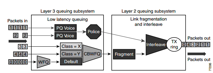 |
| Optimized Queuing for VoIP over the WAN |
Prioritization criteria for LLQ:
1) VOICE: The criterion for voice to be placed into a priority queue is the DSCP=46, or a per-hop behavior (PHB) value of EF.
2) VIDEO: The criterion for video conferencing traffic to be placed into a priority queue is a DSCP value of 34, or a PHB value of AF41. However, due to the larger packet sizes of video traffic, these packets should be placed in the priority queue only on WAN links that are faster than 768 Kbps. Link speeds below this value require packet fragmentation, but packets placed in the priority queue are not fragmented, thus smaller voice packets could be queued behind larger video packets. For links speeds of 768 Kbps or lower, video conferencing traffic should be placed in a separate class-based weighted fair queue (CBWFQ).
3) VOICE CONTROL: As the WAN links become congested, it is possible to starve the voice control signaling protocols,
thereby eliminating the ability of the IP phones to complete calls across the IP WAN. Therefore,
voice control protocols, such as H.323, MGCP, and SCCP, require their own class-based weighted fair queue. The entrance criterion for this queue is a DSCP value of 24 or a PHB value of CS3.
4) SPECIAL TRAFFIC: In some cases, certain data traffic might require better than best-effort treatment. This traffic is referred to as mission-critical data, and it is placed into one or more queues that have the required amount of bandwidth.
The queuing scheme within this class is first-in-first-out (FIFO) with a minimum allocated bandwidth.
Traffic in this class that exceeds the configured bandwidth limit is placed in the default queue.
The entrance criterion for this queue could be a TCP port number, a Layer 3 address, or a DSCP/PHB value.
5) All remaining traffic can be placed in a default queue for best-effort treatment.
If you specify the keyword fair, the queuing algorithm will be weighted fair queuing (WFQ).
source: Cisco Unified CallManager Express Solution Reference Network Design (SRND) Guide
DiffServ
DiffServ, contain 3 sets of DSCP values:
1) CS - Class Selector - for backward compatibility with old TOS standard,
2) AF - Assured Forwarding, 12 DSCP values (with four queues, and three drop priority classes
per queue)
3) EF - Expedited Forwarding, DSCP value (decimal 46)
Models for Implementing QoS
Model
|
Description
|
|---|---|
Best-effort model
|
|
Integrated services (IntServ)
1994
(RFC-1633,2211,2212) |
|
Differentiated services (DiffServ)
1998, december
RFC 2474, 2597, 2598, 3246, 4594 |
|
Benefits and Drawbacks of IntServ Model
Benefits
|
Drawbacks
|
|---|---|
|
|
Benefits and Drawbacks of DiffServ Model
Benefits
|
Drawbacks
|
|---|---|
|
|
- In addition to carrying regular data, switched campus networks can carry packets that are related to telephone calls.
- Voice over IP (VoIP), otherwise known as IP telephony(IPT), uses IP Phones that are connected to switched Ethernet ports.
- Catalyst switches can provide power to IP Phones, form trunk links with IP Phones, and provide the proper level of QoS for voice packet delivery.
Power over Ethernet
A Cisco IP Phone is like any other node on the network—it must have power to operate.
Power can come from two sources:
■ An external AC adapter (AC 48V adapters, commonly called wall warts)
■ Power over Ethernet (DC) over the network data cable
A more elegant solution is available as inline power (ILP) or Power over Ethernet (PoE).
- Here, the same 48V DC supply is provided to an IP Phone over the same unshielded twistedpair cable that is used for Ethernet connectivity.
- The DC power’s source is the Catalyst switch itself. No other power source is needed, unless an AC adapter is required as a redundant source.
- any device that can request and use inline power in a compatible manner can be used. Otherwise, if a nonpowered device such as a normal PC is plugged into the same switch port, the switch will not offer power to it.
- Catalyst switch should be connected to an uninterruptible power supply (UPS) so that it continues to receive and offer power even if the regular AC source fails. This allows an IP Phone or other powered device to be available for use even across a power failure.
Two methods provide PoE to connected devices:
■ Cisco Inline Power (ILP)—A Cisco-proprietary method developed before the IEEE 802.3af standard
■ IEEE 802.3af—A standards-based method that offers vendor interoperability
Detecting a Powered Device
- The switch always keeps the power disabled when a switch port is down.
- However, the switch must continually try to detect whether a powered device is connected to a port and request PoE.
- Switch must begin providing power if needed, so that the device can initialize and become operational. Only then will the Ethernet link be established.
- Because there are two PoE methods, a Catalyst switch tries both to detect a powered device.
- The switch also can apply several predetermined voltages to test for corresponding resistance values.
IEEE 802.3af Power Classes
Power Class Maximum Power Offered at 48V DC Notes
0 15.4 W Default class
1 4.0 W Optional class
2 7.0 W Optional class
3 15.4 W Optional class
4 Up to 50 W Optional class (802.3at) aka PoE Plus
The default class 0 is used if either the switch or the powered device does not support or doesn’t attempt the optional power class discovery.
Cisco inline power device discovery takes a totally different approach than IEEE 802.3af.
Instead of offering voltage and checking resistance, the switch sends out a 340 kHz test tone on the transmit pair of the twisted-pair Ethernet cable. A tone is transmitted instead of DC power because the switch first must detect an inline power-capable device before offering it power. Otherwise, other types of devices (normal PCs, for example) could be damaged.
Supplying Power to a Device
- A switch first offers a default power allocation to the powered device.
- On a Catalyst 3750-24-PWR, for example, an IP Phone first receives 15.4 W (0.32 amps at 48 V DC).
- The power budget offered to the device can be changed from the default to a more appropriate value.
- With IEEE 802.3af, the power budget can be changed by detecting the device’s power class.
- For Cisco ILP, the switch can attempt a Cisco Discovery Protocol (CDP) message exchange with the device.
debug ilpower controllerConfiguring PoE
debug cdp packets
- Each switch port can automatically detect the presence of an inline power-capable device before applying power, or the feature can be disabled to ensure that the port can never detect or offer inline power.
- By default, every switch port attempts to discover an inline-powered device.
- By default, every switch interface is configured for auto mode, where the device and power budget automatically is discovered.
- By default, power budget is 15.4 W
- You can change the maximum power offered as max <milli-watts> (4000 to 15400).
- never keyword - disable PoE on a switch port. Power never will be offered and powered devices never will be detected on that port.
Switch(config)# interface <type mod/num>Verifying PoE
Switch(config-if)# power inline {auto [max <milli-watts>] | static [max <milli-watts>] | never }
Switch(config-if)# power inline auto
Switch# show power inline [<type mod/num>]Example
Switch# show power inline module 3
Available:677(w) Used:117(w) Remaining:560(w)
Interface Admin Oper Power(Watts) Device Class
From PS To Device
--------- ------ ---------- ---------- ---------- ------------------- -----
Fa3/1 auto on 17.3 15.4 Ieee PD 0
Fa3/2 auto on 4.5 4.0 Ieee PD 1
Fa3/3 auto on 7.1 6.3 Cisco IP Phone 7960 0
Fa3/4 auto on 7.1 6.3 Cisco IP Phone 7960 n/a
Fa3/5 auto on 17.3 15.4 Ieee PD 0
Fa3/8 auto on 7.9 7.0 Ieee PD 2
Fa3/10 auto on 17.3 15.4 Ieee PD 4
Fa3/12 auto off 0 0 n/a n/a
...
Voice VLANs
- Cisco IP Phone provides a data connection for a user’s PC, in addition to its own voice data stream.
- The IP Phone also can control some aspects of how the packets (both voice and user data) are presented to the switch.
- Most Cisco IP Phone models contain a three-port switch, connecting to the upstream switch, the user’s PC, and the internal VoIP data stream.
- The link mode between the IP Phone and the switch is negotiated.
 |
| Cisco IP Phone Connected to a Switch |
 |
| 802.1Q Header |
The way traffic is treated when assigned to any particular class is undefined and left to the implementation.
The IEEE has made some broad recommendations:
PCP Priority Acronym Traffic TypesVLAN 0 (zero)
1 0 (lowest) BK Background
0 1 BE Best Effort
2 2 EE Excellent Effort
3 3 CA Critical Applications
4 4 VI Video, < 100 ms latency and jitter
5 5 VO Voice, < 10 ms latency and jitter
6 6 IC Internetwork Control
7 7 (highest) NC Network Control
- The VLAN ID 0 is used when a device needs to send priority-tagged frames but does not know in which particular VLAN it resides.
- The basic Ethernet frame does not have any priority field. The priority bits, also called CoS bits (Class of Service) are a part of 802.1Q VLAN tag.
- Therefore, a device needing to add a CoS marking to its frames has to insert a 802.1Q tag into each frame. However, even though this device may be capable of adding 802.1Q tags into its frames, it may not know in what VLAN it currently resides.
The frames transmitted with the 802.1Q VLAN tag set to zero and the 802.1P priority bits configured as per the priority with which the frames are to be processed. When these frames are received at the far end, the header is stripped off and the frame is processed as per the configuration of the 802.1P priority bits. If the VLAN ID has a nonzero value, the header is retained and the frame is transmitted to the specified VLAN subinterface.
Voice VLAN Configuration
- IP Phone uplink can be a trunk or nontrunk, but the real consideration is how the voice traffic will be encapsulated.
- The voice packets must be carried over a unique voice VLAN (known as the voice VLAN IDor VVID) or over the regular data VLAN (known as the native VLAN or the port VLAN ID, PVID).
- The QoS information from the voice packets also must be carried.
- To configure the IP Phone uplink, just configure the switch port where it connects.
- The switch instructs the phone to follow the mode that is selected. In addition, the switch port does not need any special trunking configuration commands if a trunk is wanted
Switch(config-if)# switchport voice vlan {<vlan-id> | dot1p | untagged | none}- The default condition for every switch port is none, where a trunk is not used.
Switch(config-if)# switchport voice vlan 9 <---configures an IP Phone to use VLAN 9 for voice traffic
- All modes except for none use the special-case 802.1Q trunk.
- The only difference between the dot1p and untagged modes is the encapsulation of voice traffic.
- The dot1p mode puts the voice packets on VLAN 0, which requires a VLAN ID (not the native VLAN) but doesn’t require a unique voice VLAN to be created.
- The untagged mode puts voice packets in the native VLAN, requiring neither a VLAN ID nor a unique voice VLAN.
- If an IP Phone is removed and a PC is connected to the same switch port, the PC still will be capable of operating because the data VLAN still will appear as the access VLAN.
Voice VLAN Configuration Guidelines
- You should configure voice VLAN on switch access ports.
- The PortFast feature is automatically enabled when voice VLAN is configured. When you disable voice VLAN, the Port Fast feature is not automatically disabled.
- When you enable port-security on an interface that is also configured with a voice VLAN, you must set the maximum allowed secure addresses on the port to at least two.
- If any type of port-security is enabled on the access VLAN, dynamic port security is automatically enabled on the voice VLAN. You cannot configure port security on a per-VLAN basis.
- You cannot configure static secure or sticky secure MAC addresses on a voice VLAN.
- Voice VLAN ports can also be these port types:
--Dynamic access port.
--Secure port.
--802.1X authenticated port.
--Protected port.

Verifying Voice VLAN Operation
- When the IP Phone trunk is active, it is not shown in the trunking mode from any Cisco IOS Software show command.
- STP runs with two instances—one for the voice VLAN and one for the data VLAN, which can be seen with the show spanning-tree interface
Switch# show interfaces fastEthernet 1/0/1 switchport
Name: Fa1/0/1
Switchport: Enabled
Administrative Mode: dynamic auto
Operational Mode: static access
Administrative Trunking Encapsulation: negotiate
Operational Trunking Encapsulation: native
Negotiation of Trunking: On
Access Mode VLAN: 10 (VLAN0010)
Trunking Native Mode VLAN: 1 (default)
Administrative Native VLAN tagging: enabled
Voice VLAN: 110 (VoIP)
Administrative private-vlan host-association: none
Administrative private-vlan mapping: none
Switch# show running-config interface fastethernet 1/0/1
interface FastEthernet1/0/1
switchport trunk native vlan 99
switchport access vlan 10 <---VLAN that carry PC Data
switchport voice vlan 110 <---VLAN that carry Voice
switchport mode access
Switch# show spanning-tree interface fastethernet 1/0/1
Vlan Role Sts Cost Prio.Nbr Type
---------------- ---- --- --------- -------- --------------------------------
VLAN0010 Desg FWD 19 128.51 P2p
VLAN0110 Desg FWD 19 128.51 P2p
Voice QoS
- On a quiet, underutilized network, a switch generally can forward packets as soon as they are received.
- Traditionally, network congestion has been handled by increasing link bandwidths and switching hardware performance.
- Quality of service (QoS) is the overall method used in a network to protect and prioritize time-critical or important traffic.
- The most important aspect of transporting voice traffic across a switched campus network is maintaining the proper QoS level.
QoS Overview
Different types of applications have different requirements for how their data should be sent end to end.
Three basic things can happen to packets as they are sent from one host to another across a network:
■ Delay— a packet delivery is delayed by some amount of time (caused by the time required to send the packet serially across a wire, the time required for a router or switch to perform table lookups or make decisions, the time required for the data to travel over a geographically long path, and so on).
The total delay from start to finish is called the latency.
This is seen most easily as the time from when a user presses a key until the time the character is echoed and displayed in a terminal session.
■ Jitter—As packets are delivered, variations can occur in the amount of delay so that they do not all arrive at predictable times.
The variation in delay is called jitter. Audio streams are particularly susceptible to jitter; if the audio data is not played back at a constant rate.
■ Loss—In extreme cases, packets that enter a congested or error-prone part of the network are simply dropped without delivery.
- Some amount of packet loss is acceptable and recoverable by applications that use a reliable, connection-oriented protocol such as TCP.
- Other application protocols are not as tolerant, and dropped packets mean data is missing.
The network can employ three basic types of QoS:
1) Best-Effort Delivery
- A network that just forwards packets in the order they were received has no real QoS.
- Switches and routers then make their “best effort” to deliver packets as quickly as possible, with no regard for the type of traffic or the need for priority service.
2) Integrated Services Model
- Prearrange a path for priority data along the complete path, from source to destination.
- RFC 1633, the Resource Reservation Protocol (RSVP) was developed as the mechanism for scheduling and reserving adequate path bandwidth for an application.
- Each network device along the way must check to see whether it can support the request.
- When a complete path meeting the minimum requirements is made, the source is signaled with a confirmation. Then the source application can begin using the path.
- does not scale very well when many sources are trying to compete with each other to reserve end-to-end bandwidth.
- applies QoS on a per-flow basis.
3) Differentiated Services Model
- permits each network device to handle packets on an individual basis.
- Each router or switch can be configured with QoS policies to follow, and forwarding decisions are made accordingly.
- requires no advance reservations; QoS is handled dynamically, in a distributed fashion.
- bases its QoS decisions on information contained in each packet header.
- applies it on a per-hop basis to a whole group of similar flows.
- Giving premium service to voice traffic focuses almost entirely on the DiffServ model.
DiffServ QoS
Layer 2 QoS Classification
Layer 2 frames themselves have no mechanism to indicate the priority or importance of their contents.
- One frame looks just as important as another. Therefore, a Layer 2 switch can forward frames only according to a best-effort delivery.
- When frames are carried from switch to switch, however, an opportunity for classification occurs.
- Using VLAN trunks, the encapsulation also includes a field that can mark the class of service (CoS) of each frame.
IEEE 802.1Q
- Each frame is tagged with a 12-bit VLAN ID and a User field.
- The User field contains three 802.1p priority bits that indicate the frame CoS, a unitless value ranging from 0 (lowest-priority delivery) to 7 (highest-priority delivery).
- Frames from the native VLAN are not tagged (no VLAN ID or User field), so they receive a default CoS that is configured on the receiving switch.
Inter-Switch Link (ISL)
- Each frame is tagged with a 15-bit VLAN ID.
- In addition, next to the frame Type field is a 4-bit User field. The lower 3 bits of the User field are used as a CoS value.
- Although ISL is not standards-based, Catalyst switches make CoS seamless by copying the 802.1p CoS bits from an 802.1Q trunk into the User CoS bits of an ISL trunk. This allows CoS information to propagate along trunks of differing encapsulations.
Layer 3 QoS Classification with DSCP
From the beginning, IP packets have always had a type of service (ToS) byte that can be used to mark packets.
This byte is divided into a 3-bit IP Precedence value and a 4-bit ToS value.
This offers a rather limited mechanism for QoS because only the 3 bits of IP Precedence are used to describe the per-hop QoS behavior.
History for IP Precedence, TOS & DSCP
1981
TOS (8bits = 3 bits IP Precedence+5bits for delay, throughput, reliability) - The Type of Service field in the IP header was originally defined in RFC 791
- It defined a mechanism for assigning a priority to each IP packet as well as a mechanism to request specific treatment such as high throughput, high reliability or low latence,
- In practice, only the IP Precedence part of the field was ever used.
- At its simplest, the higher the value of the IP Precedence field, the higher the priority of the IP packet.
| 0 | 1 | 2 | 3 | 4 | 5 | 6 | 7 |
|---|---|---|---|---|---|---|---|
| Precedence | Type of Service | ||||||
1998
- In the update version: RFC 2474 the definition of this entire field was changed.
- It is now called the "DS" (Differentiated Services) field and the upper 6 bits contain a value called the DSCP" (Differentiated Services Code Point).
        0   1   2   3   4   5   6   7
      +---+---+---+---+---+---+---+---+
      |         DSCP          |  CU   |
      +---+---+---+---+---+---+---+---+

        DSCP: differentiated services codepoint
        CU:   currently unused
2001
- Since RFC 3168, the remaining two bits (the two least siginficant bits) are used for Explicit Congestion Notification.
- allows end-to-end notification of network congestion without dropping packets. ECN is an optional feature that is only used when both endpoints support it and are willing to use it. It is only effective when supported by the underlying network.
- While Differentiated Services is somewhat backwards compatible with ToS, ECN is not.
- The Explicit Congestion Notification-Capable Transport (ECT)
- When both endpoints support ECN they mark their packets with ECT(0) or ECT(1)
- Many modern implementations of the TCP/IP protocol suite have some support for ECN; however, they usually ship with ECN disabled.
         0     1     2     3     4     5     6     7
      +-----+-----+-----+-----+-----+-----+-----+-----+
      |          DS FIELD, DSCP           | ECN FIELD |
      +-----+-----+-----+-----+-----+-----+-----+-----+

        DSCP: differentiated services codepoint
        ECN:  Explicit Congestion Notification
      +-----+-----+
      | ECN FIELD |
      +-----+-----+
        ECT   CE         [Obsolete] RFC 2481 names for the ECN bits.
         0     0         Not-ECT  - a packet that is not using ECN.
         0     1         ECT(1)
         1     0         ECT(0)
         1     1         CE       - is set by a router to indicate congestion tothe end nodes.
https://tools.ietf.org/html/rfc3168 page 6
Routers treat the ECT(0) and ECT(1) codepoints
   as equivalent.  Senders are free to use either the ECT(0) or the
   ECT(1) codepoint to indicate ECT, on a packet-by-packet basis.
DSCP
- The 6-bit DS value is known as the differentiated service codepoint (DSCP) and is the one value that is examined by any DiffServ network device.
- The DSCP value is divided into a 3-bit class selector and a 3-bit Drop Precedence value.
         0     1     2     3     4     5     6     7
      +-----+-----+-----+-----+-----+-----+-----+-----+
TOS   |  P2   P1    P0  | T3    T2    T1    T0  |  0  |   old format
+-----+-----+-----+-----+-----+-----+-----+-----+
DS    | DS5    DS4  DS3   DS2    DS1  DS0 | ECN FIELD |   new format
      +-----+-----+-----+-----+-----+-----+-----+-----+
      | Class Selector  | Drop Precedence | ECN FIELD |
      +-----+-----+-----+-----+-----+-----+-----+-----+
DSCP <=> IP Precedence Conversion Table
- Class 0, the default class, offers only best-effort forwarding.
- Cclass 1-4 - Packets in the AF classes can be dropped, if necessary, with the lower-class numbers the most likely to be dropped.
- Class 5 - EF packets - premium service. EF is the least likely to be dropped, so it always is reserved for time-critical data such as voice traffic.
- Class 6 - internetwork control.
- Class 7 - network control.
Class 6,7 - Usually, routers and switches use these classes for things such as the Spanning Tree Protocol and routing protocols. This ensures timely delivery of the packets that keep the network stable and operational.
Each class represented in the DSCP also has three levels of drop precedence
■ Low (1)
■ Medium (2)
■ High (3) - potential for being dropped before those with a lower value
| DSCP Name | DS Field Value (Dec) | Binary value | IP Precedence (Description) |
| CS0 - default | 0 | 000 000 | 0 :Best Effort |
| CS1,AF11-13 | 8,10,12,14 | 001 xxx | 1 :Priority |
| CS2,AF21-23 | 16,18,20,22 | 010 xxx | 2 :Immediate |
| CS3,AF31-33 | 24,26,28,30 | 011 xxx | 3 :Flash - mainly used for voice signaling |
| CS4,AF41-43 | 32,34,36,38 | 100 xxx | 4 :Flash Override |
| CS5,EF | 40,46 | 101 xxx | 5 :Critical - mainly used for voice RTP |
| CS6 | 48 | 110 xxx | 6 :Internet |
| CS7 | 56 | 111 xxx | 7 :Network |
Description of DSCP Name
- CS : Class Selector (RFC 2474)
- AFxy : Assured Forwarding (x=class, y=drop precedence) (RFC2597)
- EF : Expedited Forwarding (RFC 3246)

CCNA v3 (2017)
Congestion Management (Queuing)
A number of queuing algorithms are available:
- First-In, First-Out (FIFO)
- Weighted Fair Queuing (WFQ)
- Class-Based Weighted Fair Queuing (CBWFQ)
- Low Latency Queuing (LLQ)
1) FIFO
FIFO queuing—also known as first-come, first-served (FCFS) queuing—involves buffering and forwarding of packets in the order of arrival.
When FIFO is used, important or time-sensitive traffic can be dropped when congestion occurs on the router or switch interface. When no other queuing strategies are configured, all interfaces except serial interfaces at E1 (2.048 Mbps) and below use FIFO by default. (Serial interfaces at E1 and below use WFQ by default.)
FIFO, which is the fastest method of queuing, is effective for large links that have little delay and minimal congestion. If your link has very little congestion, FIFO queuing may be the only queuing you need to use.
2) WFQ
Weighted Fair Queuing - is an automated scheduling method that provides fair bandwidth allocation to all network traffic. WFQ applies priority, or weights, to identified traffic and classifies it into conversations or flows
WFQ classifies traffic into different flows based on packet header addressing, including such characteristics as source and destination IP addresses, MAC addresses, port numbers, protocol, and Type of Service (ToS) value. The ToS value in the IP header can be used to classify traffic.
WFQ is not supported with tunneling and encryption because these features modify the packet content information required by WFQ for classification.
Although WFQ automatically adapts to changing network traffic conditions, it does not offer the degree of precision control over bandwidth allocation that CBWFQ offers.
3) CBWFQ
CBWFQ extends the standard WFQ functionality to provide support for user-defined traffic classes.
A FIFO queue is reserved for each class, and traffic belonging to a class is directed to the queue for that class.
To characterize a class, you assign it bandwidth, weight, and maximum packet limit. The bandwidth assigned to a class is the guaranteed bandwidth delivered to the class during congestion.
After a queue has reached its configured queue limit, adding more packets to the class causes tail drop or packet drop to take effect, depending on how class policy is configured. Tail drop means a router simply discards any packet that arrive at the tail end of a queue that has completely used up its packet-holding resources. This is the default queuing response to congestion. Tail drop treats all traffic equally and does not differentiate between classes of service.
Round robin scheduling includes the concept of weighting (generally called weighted round robin).
For example, routers use a popular tool called Class-Based Weighted Fair Queuing (CBWFQ) to guarantee a minimum amount of bandwidth to each class.
CBWFQ uses a weighted round robin scheduling algorithm, while letting the network engineer define the weightings as a percentage of link bandwidth.
Example:
Queue1 - 20%
Queue2 - 30%
Queue3 - 50%
If the outgoing link is congested, the scheduler guarantees the percentage bandwidth shown to each queue.
That is, Queue1 gets 20 percent of the link even during busy times.
A round robin queuing system adds too much delay for these voice and video packets.
Use a round robin queuing method like CBWFQ for data classes and for noninteractive voice and video.
4) LLQ
Low Latency Queuing (always next).
The LLQ feature brings strict priority queuing (PQ) to CBWFQ. Strict PQ allows delay-sensitive data such as voice to be sent before packets in other queues. LLQ provides strict priority queuing for CBWFQ, reducing jitter in voice conversationsThe LLQ feature brings strict priority queuing (PQ) to CBWFQ. Strict PQ allows delay-sensitive data such as voice to be sent before packets in other queues. LLQ provides strict priority queuing for CBWFQ, reducing jitter in voice conversations.
Without LLQ, CBWFQ provides WFQ based on defined classes with no strict priority queue available for real-time traffic. The weight for a packet belonging to a specific class is derived from the bandwidth you assigned to the class when you configured it.
With LLQ, delay-sensitive data is sent first, before packets in other queues are treated. LLQ allows delay-sensitive data such as voice to be sent first (before packets in other queues), giving delay-sensitive data preferential treatment over other traffic. Although it is possible to enqueue various types of real-time traffic to the strict priority queue, Cisco recommends that only voice traffic be directed to it.
LLQ, tells the scheduler to treat one or more queues as special priority queues.
The LLQ scheduler always takes the next message from one of these special priority queues.
Plus the queue never has time to fill up, so there are no drops due to the queue filling up.
The scheduler never services the other queues (called "queue starvation").
Limiting the amount of bandwidth in the priority queue protects the other queues, but it
causes yet another problem.
Find a way to limit the amount of voice and video that the network
routes out this link, so that the policer never discards any of the traffic.
There are QoS tools to help you do just that, called Call Admission Control (CAC) tools.
====Shaping and Policing
Classification and marking can be done on ingress or egress,
whereas other QoS actions such queuing and shaping are usually done on egress.
Both policing and shaping monitor the bit rate of the combined messages that flow through a device.
Once enabled, the policer or shaper notes each packet that passes, and measures the number of bits per second over time.
Policing makes sense only in certain cases, and as a general tool, it can be best used at the edge between two networks.
■ It measures the traffic rate over time for comparison to the configured policing rate.
■ It allows for a burst of data after a period of inactivity.
■ It is enabled on an interface, in either direction, but typically at ingress.
■ It can discard excess messages, but can also re-mark the message so that it is a candidate for more aggressive discard later in its journey.
Shapers make sense when a device can send at a certain speed, but there is a benefit to slowing down the rate.
The shaper slows messages down by queuing the messages.
A shaper basically sends as fast as it can, and then waits; sends and waits; sends and waits.
The solution to this problem: configure a short time interval.
By recommendation, use a 10-ms time interval to support voice and video.
Key features of shapers:
■ Shapers measure the traffic rate over time for comparison to the configured shaping rate.
■ Shapers allow for bursting after a period of inactivity.
■ Shapers are enabled on an interface for egress (outgoing packets).
■ Shapers slow down packets by queuing them, and over time releasing them from the queue at the shaping rate.
■ Shapers use queuing tools to create and schedule the shaping queues,
which is very important for the same reasons discussed for output queuing.
=====Congestion Avoidance
TCP Windowing Basics
TCP uses a flow control mechanism called windowing.
Each TCP receiver grants a window to the sender.
The window, which is a number, defines the number of bytes the sender can send over the TCP connection
before receiving a TCP acknowledgement for at least some of those bytes.
Each TCP connection has two senders and two receivers; that is, each host sends and receives data.
The worse the congestion in the queues, the more likely tail drop will occur.
In the same queue, packets with one marking might be dropped more aggressively, and those with better DSCP markings dropped less aggressively.
If the number of packets to be queued continues to increase, the memory queues fill up and packets are dropped.
The following approaches can prevent drops in sensitive applications:- Increase link capacity to ease or prevent congestion.
- Guarantee enough bandwidth and increase buffer space to accommodate bursts of traffic from fragile flows. There are several mechanisms available in Cisco IOS QoS software that can guarantee bandwidth and provide prioritized forwarding to drop-sensitive applications. Examples being WFQ, CBWFQ, and LLQ.
- Prevent congestion by dropping lower-priority packets before congestion occurs. Cisco IOS QoS provides queuing mechanisms that start dropping lower-priority packets before congestion occurs. An example being weighted random early detection (WRED).
Implementing QoS for Voice
Classification
- Process to manipulate packets according to QoS policies, a switch somehow must identify which level of service each packet should receive.
- IP packets carry a ToS or DSCP value within their headers as they travel around a network,
- Frames on a trunk also can have CoS values associated with them.
- A switch then can decide whether to trust the ToS, DSCP, or CoS values already assigned to inbound packets. If it trusts any of these values, the values are carried over and used to make QoS decisions inside the switch.
- If the QoS values are not trusted, they can be reassigned or overruled.
- Every switch must decide whether to trust incoming QoS values.
- The perimeter formed by switches that do not trust incoming QoS is called the trust boundary.
Configuring a Trust Boundary
- When a Cisco IP Phone is connected to a switch port, think of the phone as another switch (which it is), you probably can trust the QoS information relayed by the phone.
- IP Phone also has two sources of data: VoIP packets native to the phone and user PC data switch port.
1) Enable QoS on the switch
Switch(config)# mls qos2) Define the QoS parameter that will be trusted:
! By default, QoS is disabled globally on a switch and all QoS information is allowed to pass from one switch port to another.
! When you enable QoS, all switch ports are configured as untrusted, by default.
Switch(config)# interface <type mod/num>3) Make (optional) the trust conditional:
Switch(config-if)# mls qos trust {cos | ip-precedence | dscp}
! Only one of these parameters can be selected.
! Generally, for Cisco IP Phones, you should use the cos
Switch(config-if)# mls qos trust device cisco-phone4) Instruct the IP Phone on how to extend the trust boundary:
! If used, the QoS parameter defined in Step 2 is trusted only if a Cisco IP Phone is detected through CDP.
! If a phone is not detected, the QoS parameter is not trusted.
Switch(config-if)# switchport priority extend {cos <value> | trust}5) Switch uplinks always should be considered as trusted ports—as long as they connect to other trusted devices that are within the QoS boundary.
! QoS information from a PC connected to an IP Phone should not be trusted
! If CoS values from the PC cannot be trusted, they should be overwritten to a value of 0.|
Switch(config-if)# switchport priority extend cos 1 <---IP Phone should mark all incoming traffic from an attached PC to have CoS 1
Switch(config)# interface <type mod/num>Auto-QoS
Switch(config-if)# mls qos trust cos
! the trust is not conditional
- To reduce the complexity of QoS configuration, Cisco introduced the Auto-QoS feature on most switch platforms.
- By entering only a couple of configuration commands, you can enable the switch to automatically configure a variety of QoS parameters.
- Auto-QoS is actually handled by a macro command, which in turn enters many other configuration commands as if they were entered from the command-line interface.
Select an interface at the QoS boundary:
Switch(config)# interface <type mod/num>Enable Auto-QoS with the appropriate trust:
Switch(config-if)# auto qos voip {cisco-phone | cisco-softphone | trust}Verifying Voice QoS
! If the switch port is connected to a Cisco IP Phone, you should use the cisco-phone
! If no phone is connected, the port is considered untrusted.
! If a PC running the Cisco SoftPhone application is connected, choose the cisco-softphone
! On a switch port acting as an uplink to another switch or router, you should use the trust
To verify how QoS trust has been extended to the IP Phone itself
Switch# show mls qos interface <type mod/num>Example
Switch# show mls qos interface fastethernet 0/1Another command:
FastEthernet0/1
trust state: trust cos
trust mode: trust cos
trust enabled flag: ena
COS override: dis
default COS: 0
DSCP Mutation Map: Default DSCP Mutation Map
Trust device: none <--verify how the IP Phone has been instructed to treat incoming QoS information from its attached PC or other device
Switch# show interface <type mod/num> switchportIf the switch port were configured with the switchport priority extend trust command, the appliance trust would show trusted
Switch# show interface fastethernet 0/1 switchport
Name: Fa0/1
Switchport: Enabled
[output deleted...]
Voice VLAN: 2 (VLAN0002)
Appliance trust: none <---IP Phone’s device is not being trusted
If the IP Phone is not connected to the switch port, it is not detected and the trust parameter is not enabled
Switch# show mls qos interface fastethernet 0/1When a Cisco IP Phone is connected, power is applied and the phone is detected. Then the conditional QoS trust (CoS, in this case) is enabled
FastEthernet0/1
trust state: not trusted
trust mode: trust cos
trust enabled flag: dis
COS override: dis
default COS: 0
DSCP Mutation Map: Default DSCP Mutation Map
Trust device: cisco-phone
Switch#
Switch# show mls qos interface fastethernet 1/0/1
FastEthernet1/0/1
trust state: trust cos
trust mode: trust cos
trust enabled flag: ena
COS override: dis
default COS: 0
DSCP Mutation Map: Default DSCP Mutation Map
Trust device: cisco-phone
Switch#