Binary notation is a representation of information using only ones and zeros. Computers communicate using binary data.
Binary Numbering System
The base 2 numbering system only has two digits: 0 and 1.
Each position represents increasing powers of 2. In 8-bit binary numbers, the positions represent these quantities:
2^7 2^6 2^5 2^4 2^3 2^2 2^1 2^0
128 64 32 16 8 4 2 1
1111'1111
128 + 64 + 32 + 16 + 8 + 4 + 2 + 1 = 255
0000'0000
0 + 0 + 0 + 0 + 0 + 0 + 0 + 0 = 0
 |
| Decimal to binary table |
An IP address is a hierarchical address that is made up of two parts: a network portion and a host portion.
The bits within the network portion of the address must be identical for all devices that reside in the same network.

The subnet mask is represented in dotted decimal format for ease of use.
The subnet mask is configured on a host device, in conjunction with the IPv4 address, and is required so the host can determine which network it belongs to.
The prefix length is another way of expressing the subnet mask.
“Slash notation”, a “/” followed by the number of bits set to 1.
Network Address - 10.1.1.0/24
The network address is a standard way to refer to a network.
The IPv4 host address is logically ANDed, bit by bit, with its subnet mask to determine the network address to which the host is associated.
First Host Address - 10.1.1.1/24
Host Address - 10.1.1.34/24
Every end device requires a unique address to communicate on the network. In IPv4 addresses, the values between the network address and the broadcast address can be assigned to end devices in a network.
Last Host Address - 10.1.1.254/24
Broadcast Address - 10.1.1.255/24
The IPv4 broadcast address is a special address for each network that allows communication to all the hosts in that network.
IPv4 Unicast, Broadcast, and Multicast
With a static assignment, the network administrator must manually configure the network information for a host.
There are several advantages to static addressing. For instance, they are useful for printers, servers, and other networking devices that do not change location often and need to be accessible to clients on the network based on a fixed IP address.
When using static IP addressing, it is necessary to maintain an accurate list of the IP address assigned to each device. These are permanent addresses and are not normally reused.
DHCP enables the automatic assignment of addressing information such as IP address, subnet mask, default gateway, and other configuration information.
DHCP is generally the preferred method of assigning IPv4 addresses to hosts on large networks because it reduces the burden on network support staff and virtually eliminates entry errors.
Another benefit of DHCP is that an address is not permanently assigned to a host but is only "leased" for a period of time. If the host is powered down or taken off the network, the address is returned to the pool for reuse. This feature is especially helpful for mobile users that come and go on a network.
In an IPv4 network, the hosts can communicate one of three ways:
- Unicast - The process of sending a packet from one host to an individual host (used for normal host-to-host communication in both a client/server and a peer-to-peer networ)
IP address range of 0.0.0.0 to 223.255.255.255
- Broadcast - The process of sending a packet from one host to all hosts in the network (used to send packets to all hosts in the network using the broadcast address for the network)
Many network protocols, such as DHCP, use broadcasts. When a host receives a packet sent to the network broadcast address, the host processes the packet as it would a packet addressed to its unicast address.
Broadcast packets are usually restricted to the local network
Directed Broadcast - is sent to all hosts on a specific network. 172.16.4.255 for 172.16.4.0/24
Although routers do not forward directed broadcasts by default, they may be configured to do so.
Limited Broadcast - for communication that is limited to the hosts on the local network. IP is 255.255.255.255
Routers do not forward a limited broadcast.
Limited broadcast reaches the NICs in the network segment, routers don't forward it, so it's limited. Directed will reach all the hosts in the network if it's allowed by a router, so it's directed.
Because routers separate broadcast domains, subdividing networks with excessive broadcast traffic can improve network performance.
DHCP packets are Limited broadcast packets and NBNS uses directed broadcast packets.
- Multicast - The process of sending a packet from one host to a selected group of hosts, possibly in different networks.
Multicast transmission is designed to conserve the bandwidth of an IPv4 network.
It reduces traffic by allowing a host to send a single packet to a selected set of hosts that are part of a subscribing multicast group.
With multicast, the source host can send a single packet that can reach thousands of destination hosts. The internetwork’s responsibility is to replicate the multicast flows in an efficient manner so that they reach only their intended recipients.
Some examples of multicast transmission are:
- Video and audio broadcasts
- Routing information exchange by routing protocols
- Distribution of software
- Remote gaming.
This address range is 224.0.0.0 to 239.255.255.255 (224.0.0.0/4)
The IPv4 multicast addresses 224.0.0.0 to 224.0.0.255 are reserved link local addresses. These addresses are to be used for multicast groups on a local network.
The globally scoped addresses are 224.0.1.0 to 238.255.255.255. They may be used to multicast data across the Internet.
For example, 224.0.1.1 has been reserved for the Network Time Protocol (NTP) to synchronize the time-of-day clocks of network devices.
Types of IPv4 Addresses
Although most IPv4 host addresses are public addresses designated for use in networks that are accessible on the Internet, there are blocks of addresses that are used in networks that require limited or no Internet access. These addresses are called private addresses.
Private addresses are defined in RFC 1918.
Hosts in different networks may use the same private space addresses.
Packets using these addresses as the source or destination should not appear on the public Internet.
The router or firewall device at the perimeter of these private networks must block or translate these addresses.
The private address blocks are:
- 10.0.0.0 to 10.255.255.255 (10.0.0.0/8)
- 172.16.0.0 to 172.31.255.255 (172.16.0.0/12)
- 192.168.0.0 to 192.168.255.255 (192.168.0.0/16)
Network and Broadcast Addresses
Loopback
Although only the single 127.0.0.1 address is used, addresses 127.0.0.0 to 127.255.255.255 are reserved
Any address within this block will loop back to the local host. No address within this block should ever appear on any network.
Link-Local Addresses
IPv4 addresses in the address block 169.254.0.0 to 169.254.255.255 (169.254.0.0/16).
These addresses can be automatically assigned to the local host by the operating system in environments where no IP configuration is available.
These might be used in a small peer-to-peer network or for a host that could not automatically obtain an address from a DHCP server.
Communication using IPv4 link-local addresses is only suitable for communication with other devices connected to the same network.
TEST-NET Addresses
The address block 192.0.2.0 to 192.0.2.255 (192.0.2.0/24) is set aside for teaching and learning purposes.
These addresses can be used in documentation and network examples. Unlike the experimental addresses, network devices will accept these addresses in their configurations.
Addresses within this block should not appear on the Internet.
Experimental Addresses
The addresses in the block 240.0.0.0 to 255.255.255.254 are listed as reserved for future use (RFC 3330).
Currently, these addresses can only be used for research or experimentation purposes, but cannot be used in an IPv4 network.
Classfull addressing
Classful allocation of address space often wasted many addresses, which exhausted the availability of IPv4 addresses.
Class A Blocks 0.0.0.0/8 to 127.0.0.0/8
Class B Blocks 128.0.0.0/16 to 191.255.0.0/16
Class C Blocks 192.0.0.0/24 to 223.255.255.0/24
Classless Addressing
The system in use today is referred to as classless addressing. The formal name is Classless Inter-Domain Routing (CIDR, pronounced “cider”).
IP space organizations
IANA (Internet Assigned Numbers Authority) http://www.iana.org manages the allocation of IPv4 and IPv6 addresses.
These registration companies are called Regional Internet Registries (RIRs) - manage for particular purposes or for regional areas:
- AfriNIC (African Network Information Centre) - Africa Region http://www.afrinic.net
- APNIC (Asia Pacific Network Information Centre) - Asia/Pacific Region http://www.apnic.net
- ARIN (American Registry for Internet Numbers) - North America Region http://www.arin.net
- LACNIC (Regional Latin-American and Caribbean IP Address Registry) - Latin America and some Caribbean Islands http://www.lacnic.net
- RIPE NCC (Reseaux IP Europeans) - Europe, the Middle East, and Central Asia http://www.ripe.net
 |
| IANA RIRs |
RIRs are responsible for allocating IP addresses to the Internet Service Providers (ISPs). Most companies or organizations obtain their IPv4 address blocks from an ISP. An ISP will generally supply a small number of usable IPv4 addresses (6 or 14) to their customers as a part of their services. Larger blocks of addresses can be obtained based on justification of needs and for additional service costs.
IPv6 addresses can be obtained from the ISP or in some cases directly from the RIR.
ISP Tiers
Tier 1
Large national or international ISPs that are directly connected to the Internet backbone. Highly reliable connections and services. The primary advantages for customers of Tier 1 ISPs are reliability and speed. The drawback for Tier 1 ISP customers is its high cost.
Tier 1 ISPsTier 2
AT&T United States
CenturyLink (formerly Qwest and Savvis) United States
Deutsche Telekom Germany
XO Communications United States
GTT (formerly Tinet) United States
Verizon Business (formerly UUNET) United States
Sprint United States
TeliaSonera Sweden - Finland
NTT Communications (formerly Verio) Japan
Level 3 Comm
(formerly Level 3 and Global Crossing) United States
Tata Communications India
Zayo Group formerly AboveNet United States
Tier 2 ISPs acquire their Internet service from Tier 1 ISPs. Tier 2 ISPs generally focus on business customers. These Tier 2 ISPs tend to have the IT resources to operate their own services such as DNS, email servers, and web servers. Other services that Tier 2 ISPs may offer include website development and maintenance, e-commerce/e-business, and VoIP.
Tier 3
Tier 3 ISPs purchase their Internet service from Tier 2 ISPs.
The focus of these ISPs is the retail and home markets in a specific locale. Tier 3 customers typically do not need many of the services required by Tier 2 customers. Their primary need is connectivity and support.
IPv6 Network Addresses
IPv6 has a larger 128-bit address space, providing for 340 undecillion addresses. (That is the number 340, followed by 36 zeroes.)
The depletion of IPv4 address space has been the motivating factor for moving to IPv6.
On Monday, January 31, 2011, IANA allocated the last two /8 IPv4 address blocks to the Regional Internet Registries (RIRs).
IPv4 has theoretical maximum of 4.3 billion addresses. RFC 1918 private addresses in combination with Network Address Translation (NAT) have been instrumental in slowing the depletion of IPv4 address space. NAT has limitations that severely impede peer-to-peer communications.
With an increasing Internet population, a limited IPv4 address space, issues with NAT and an Internet of things, the time has come to begin the transition to IPv6.
The migration techniques can be divided into three categories:
- Dual Stack – allows IPv4 and IPv6 to coexist on the same network. Dual stack devices run both IPv4 and IPv6 protocol stacks simultaneously.
- Tunneling – is a method of transporting an IPv6 packet over an IPv4 network. The IPv6 packet is encapsulated inside an IPv4 packet, similar to other types of data.
- Translation – Network Address Translation 64 (NAT64) allows IPv6-enabled devices to communicate with IPv4-enabled devices using a translation technique similar to NAT for IPv4. An IPv6 packet is translated to an IPv4 packet, and vice versa.
Unlike IPv4 addresses that are expressed in dotted decimal notation, IPv6 addresses are represented using hexadecimal values.
Hexadecimal is usually represented in text by the value preceded by 0x (for example 0x73) or a subscript 16. Less commonly, it may be followed by an H, for example 73H.
The preferred format for writing an IPv6 address is x:x:x:x:x:x:x:x, with each “x” consisting of four hexadecimal values.
The first rule to help reduce the notation of IPv6 addresses is any leading 0s (zeros) in any 16-bit section or hextet can be omitted. For example:
- 01AB can be represented as 1AB
- 09F0 can be represented as 9F0
- 0A00 can be represented as A00
- 00AB can be represented as AB
This rule only applies to leading 0s, NOT to trailing 0s, otherwise the address would be ambiguous. For example, the hextet “ABC” could be either “0ABC” or “ABC0”.
The second rule to help reduce the notation of IPv6 addresses is that a double colon (::) can replace any single, contiguous string of one or more 16-bit segments (hextets) consisting of all 0s.
The double colon (::) can only be used once within an address
2001:0000:0DB8:1111:0000:0000:0000:0200
2001: 0: DB8:1111 :: 200
There are three types of IPv6 addresses:
- Unicast - An IPv6 unicast address uniquely identifies an interface on an IPv6-enabled device. As shown in the figure, a source IPv6 address must be a unicast address.
- Multicast - An IPv6 multicast address is used to send a single IPv6 packet to multiple destinations.
- Anycast - An IPv6 anycast address is any IPv6 unicast address that can be assigned to multiple devices. A packet sent to an anycast address is routed to the nearest device having that address. Anycast addresses are beyond the scope of this course.
Unlike IPv4, IPv6 does not have a broadcast address. However, there is an IPv6 all-nodes multicast address that essentially gives the same result.
IPv6 uses the prefix length to represent the prefix portion of the address.
IPv6 does not use the dotted-decimal subnet mask notation. The prefix length is used to indicate the network portion of an IPv6 address using the IPv6 address/prefix length.
 The prefix length can range from 0 to 128. A typical IPv6 prefix length
for LANs and most other types of networks is /64. This means the prefix
or network portion of the address is 64 bits in length, leaving another
64 bits for the interface ID (host portion) of the address.
The prefix length can range from 0 to 128. A typical IPv6 prefix length
for LANs and most other types of networks is /64. This means the prefix
or network portion of the address is 64 bits in length, leaving another
64 bits for the interface ID (host portion) of the address.
- Unicast - An IPv6 unicast address uniquely identifies an interface on an IPv6-enabled device. As shown in the figure, a source IPv6 address must be a unicast address.
- Multicast - An IPv6 multicast address is used to send a single IPv6 packet to multiple destinations.
- Anycast - An IPv6 anycast address is any IPv6 unicast address that can be assigned to multiple devices. A packet sent to an anycast address is routed to the nearest device having that address. Anycast addresses are beyond the scope of this course.
Unlike IPv4, IPv6 does not have a broadcast address. However, there is an IPv6 all-nodes multicast address that essentially gives the same result.
IPv6 uses the prefix length to represent the prefix portion of the address.
IPv6 does not use the dotted-decimal subnet mask notation. The prefix length is used to indicate the network portion of an IPv6 address using the IPv6 address/prefix length.
IPv6 unicast addresses
There are six types of IPv6 unicast addresses.
1) Global unicast - is similar to a public IPv4 address. These are globally unique, Internet routable addresses. Global unicast addresses can be configured statically or assigned dynamically. There are some important differences in how a device receives its IPv6 address dynamically compared to DHCP for IPv4.
2) Link-local - are used to communicate with other devices on the same local link. With IPv6, the term link refers to a subnet. Link-local addresses are confined to a single link. Their uniqueness must only be confirmed on that link because they are not routable beyond the link. In other words, routers will not forward packets with a link-local source or destination address.
IPv6 link-local addresses are also used by IPv6 routing protocols to exchange messages and as the next-hop address in the IPv6 routing table.
If a link-local address is not configured manually on an interface, the device will automatically create its own without communicating with a DHCP server. IPv6-enabled hosts create an IPv6 link-local address even if the device has not been assigned a global unicast IPv6 address. This allows IPv6-enabled devices to communicate with other IPv6-enabled devices on the same subnet. This includes communication with the default gateway (router).
3) Loopback - is used by a host to send a packet to itself and cannot be assigned to a physical interface. Similar to an IPv4 loopback address, you can ping an IPv6 loopback address to test the configuration of TCP/IP on the local host. The IPv6 loopback address is all-0s except for the last bit, represented as ::1/128 or just ::1 in the compressed format.
4) Unspecified address - is an all-0s address represented in the compressed format as ::/128 or just :: in the compressed format. It cannot be assigned to an interface and is only be used as a source address in an IPv6 packet. An unspecified address is used as a source address when the device does not yet have a permanent IPv6 address or when the source of the packet is irrelevant to the destination.
5) Unique local - have some similarity to RFC 1918 private addresses for IPv4, but there are significant differences as well. Unique local addresses are used for local addressing within a site or between a limited number of sites. These addresses should not be routable in the global IPv6. Unique local addresses are in the range of FC00::/7 to FDFF::/7.
Note: The original IPv6 specification defined site-local addresses for a similar purpose, using the prefix range FEC0::/10. There were several ambiguities in the specification and site-local addresses were deprecated by the IETF in favor of unique local addresses.
6) IPv4 embedded - is the IPv4 embedded address. These addresses are used to help transition from IPv4 to IPv6. IPv4 embedded addresses are beyond the scope of this course.
IPv6 global unicast
IPv6 global unicast addresses are globally unique and routable on the IPv6 Internet.
Currently, only global unicast addresses with the first three bits of 001 or 2000::/3 are being assigned.
This is only 1/8th of the total available IPv6 address space, excluding only a very small portion for other types of unicast and multicast addresses.
Global Routing Prefix
The global routing prefix is the prefix, or network, portion of the address that is assigned by the provider, such as an ISP, to a customer or site. Currently, RIRs assign a /48 global routing prefix to customers. This is more than enough address space for most customers.
Subnet ID
The Subnet ID is used by an organization to identify subnets within its site.
Interface ID
The IPv6 Interface ID is equivalent to the host portion of an IPv4 address. The term Interface ID is used because a single host may have multiple interfaces, each having one or more IPv6 addresses.
Note: Unlike IPv4, in IPv6, the all-0s address can be assigned to a device because there are no broadcast addresses in IPv6. However, the all-0s address is reserved as a Subnet-Router anycast address, and should be assigned only to routers.
IPv6 Configuration
Router
Most IPv6 configuration and verification commands in the Cisco IOS are similar to their IPv4 counterparts. In many cases the only difference is the use of ipv6 in place of ip within the commands.
ipv6 address ipv6-address/prefix-length
Router(config)#interface GigabitEthernet 0/0Host Configuration
Router(config-if)#ipv6 address 2001:db8:acad:1::1/64
Router(config-if)#no shutdown
Manually configuring the IPv6 address on a host is similar to configuring an IPv4 address.
There are two ways in which a device can obtain an IPv6 global unicast address automatically:
- SLAAC (Stateless Address Autoconfiguration) - allows a device to obtain its prefix, prefix length, and default gateway address information from an IPv6 router without the use of a DHCPv6 server,
IPv6 routers periodically send out ICMPv6 Router Advertisement (RA) messages to all IPv6-enabled devices on the network. By default, Cisco routers send out RA messages every 200 seconds to the IPv6 all-nodes multicast group address. An IPv6 device on the network does not have to wait for these periodic RA messages. A device can send a Router Solicitation (RS) message to the router, using the IPv6 all-routers multicast group address. When an IPv6 router receives an RS message it will immediately respond with a router advertisement.
- DHCPv6 - A device can automatically receive its addressing information including a global unicast address, prefix length, default gateway address and the addresses of DNS servers using the services of a DHCPv6 server.
The Interface ID
If the client does not use the information contained within the RA message and relies solely on DHCPv6, then the DHCPv6 server will provide the entire IPv6 global unicast address, including the prefix and the Interface ID.
However, if option 1 (SLAAC only) or option 2 (SLAAC with DHCPv6) is used, the client does not obtain the actual Interface ID portion of the address from this processes. The client device must determine its own 64-bit Interface ID, either by using the EUI-64 process or by generating a random 64-bit number.
An IPv6 router is a router that:
- Forwards IPv6 packets between networks,
- Can be configured with static IPv6 routes or a dynamic IPv6 routing protocol,
- Sends ICMPv6 RA messages.
IPv6 routing is not enabled by default.
To enable a router as an IPv6 router, the ipv6 unicast-routing global configuration command must be used.
Note: Cisco routers are enabled as IPv4 routers by default.
The ICMPv6 RA message contains the prefix, prefix length, and other information for the IPv6 device. The RA message also informs the IPv6 device how to obtain its addressing information:
- Option 1 - SLAAC Only – The device should use the prefix, prefix-length, and default gateway address information contained in the RA message. No other information is available from a DHCPv6 server.
- Option 2 – SLAAC and DHCPv6 – The device should use the prefix, prefix-length, and default gateway address information in the RA message. There is other information available from a DHCPv6 server such as the DNS server address. The device will, through the normal process of discovering and querying a DHCPv6 server, obtain this additional information. This is known as stateless DHCPv6 because the DHCPv6 server does not need to allocate or keep track of any IPv6 address assignments, but only provide additional information such as the DNS server address.
- Option 3 – DHCPv6 only – The device should not use the information in this RA message for its addressing information. Instead, the device will use the normal process of discovering and querying a DHCPv6 server to obtain all of its addressing information. This includes an IPv6 global unicast address, prefix length, a default gateway address, and the addresses of DNS servers. In this case, the DHCPv6 server is acting as a stateful DHCP server similar to DHCP for IPv4. The DHCPv6 server allocates and keeps track of IPv6 addresses so it does not assign the same IPv6 address to multiple devices.
Routers send ICMPv6 RA messages using the link-local address as the source IPv6 address. Devices using SLAAC use the router’s link-local address as their default gateway address.
A device may also be configured with more than one default gateway IPv6 address. For further information about how the decision is made regarding which address is used as a source IPv6 address or which default gateway address is used, refer to RFC 6724, Default Address Selection for IPv6.
EUI-64 Process
IEEE defined the Extended Unique Identifier (EUI) or modified EUI-64 process. This process uses a client’s 48-bit Ethernet MAC address, and inserts another 16 bits in the middle of the 48-bit MAC address to create a 64-bit Interface ID.
An EUI-64 Interface ID is represented in binary and is made up of three parts:
- 24-bit OUI from the client MAC address, but the 7th bit (the Universally/Locally (U/L) bit) is reversed. This means that if the 7th bit is a 0 it becomes a 1, and vice versa.
- The inserted 16-bit value FFFE (in hexadecimal),
- 24-bit Device Identifier from the client MAC address.
The advantage of EUI-64 is the Ethernet MAC address can be used to determine the Interface ID. It also allows network administrators to easily track an IPv6 address to an end-device using the unique MAC address. However, this has caused privacy concerns among many users. They are concerned that their packets can be traced to the actual physical computer. Due to these concerns, a randomly generated Interface ID may be used instead.
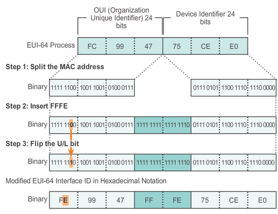 |
| IPv6 EUI-64 proccess |
Depending upon the operating system, a device may use a randomly generated Interface ID instead of using the MAC address and the EUI-64 process. For example, beginning with Windows Vista, Windows uses a randomly generated Interface ID instead of one created with EUI-64. Windows XP and previous Windows operating systems used EUI-64.
 |
| IPv6 Link Local Address generation |
- A host uses the link-local address of the local router for its default gateway IPv6 address.
- Routers exchange dynamic routing protocol messages using link-local addresses.
- Routers’ routing tables use the link-local address to identify the next-hop router when forwarding IPv6 packets.
A link-local address can be established dynamically or configured manually as a static link-local address.
Dynamically Assigned Link-Local Address
By default, Cisco IOS routers use EUI-64 to generate the Interface ID for all link-local address on IPv6 interfaces. For serial interfaces, the router will use the MAC address of an Ethernet interface.
However, a drawback to using the dynamically assigned link-local address is its length, which makes it challenging to identify and remember assigned addresses.
Static Link-Local Address
Configuring the link-local address manually provides the ability to create an address that is recognizable and easier to remember.
Router(config-if)#ipv6 address link-local-address link-localSimilar to R1, router R2 would be configured with FE80::2 as the IPv6 link-local address on all of its interfaces
Router(config-if)#ipv6 address FE80::1 link-local
Verify IPv6
show interface - command displays the MAC address of the Ethernet interfaces.
show ipv6 interface brief - displays abbreviated output for each of the interfaces, if [up/up]
show ipv6 route - can be used to verify that IPv6 networks and specific IPv6 interface addresses have been installed in the IPv6 routing table
IPv6 Multicast Addresses
IPv6 multicast addresses have the prefix FF00::/8.
Note: Multicast addresses can only be destination addresses and not source addresses.
There are two types of IPv6 multicast addresses:
- Assigned multicast - reserved multicast addresses for predefined groups of devices
FF02::1 All-nodes multicast group
Received and processed by all IPv6 interfaces on the link or network.
This has the same effect as a broadcast address in IPv4.
FF02::2 All-routers multicast group
A router becomes a member of this group when it is enabled as an IPv6 router with the ipv6 unicast-routing global configuration command. A packet sent to this group is received and processed by all IPv6 routers on the link or network.
IPv6-enabled devices send ICMPv6 Router Solicitation (RS) messages to the all-routers multicast address. The RS message requests an RA message from the IPv6 router to assist the device in its address configuration.
- Solicited node multicast - is IPV6 equivelent to what is ARP in IPv4 is (read this)
is an address that matches only the last 24 bits of the IPv6 global unicast address of a device. Is similar to the all-nodes multicast address
An IPv6 solicited-node multicast address is automatically created when the global unicast or link-local unicast addresses are assigned. The IPv6 solicited-node multicast address is created by combining a special FF02:0:0:0:0:FF00::/104 prefix with the far right 24 bits of its unicast address.
The solicited-node multicast address consists of two parts:
- FF02:0:0:0:0:FF00::/104 multicast prefix – This is the first 104 bits of the all solicited-node multicast address.
- Least significant 24-bits – These are the last or far right 24 bits of the solicited-node multicast address. These bits are copied from the far right 24 bits of the global unicast or link-local unicast address of the device.
It is possible that multiple devices will have the same solicited-node multicast address. Although rare, this can occur when devices have the same far right 24 bits in their Interface IDs. This does not create any problems because the device will still process the encapsulated message, which will include the complete IPv6 address of the device in question.
 |
| IPv6 solicited multicast address |
Although IP is not a reliable protocol, the TCP/IP suite does provide for messages to be sent in the event of certain errors. These messages are sent using the services of ICMP. The purpose of these messages is to provide feedback about issues related to the processing of IP packets under certain conditions, not to make IP reliable. ICMP messages are not required and are often not allowed within a network for security reasons.
ICMP is available for both IPv4 and IPv6. ICMPv4 is the messaging protocol for IPv4. ICMPv6 provides these same services for IPv6 but includes additional functionality. In this course, the term ICMP will be used when referring to both ICMPv4 and ICMPv6.
ICMP messages common to both ICMPv4 and ICMPv6 include:
- Host confirmation
Echo Request /Echo Reply
- Destination or Service Unreachable
When a host or gateway receives a packet that it cannot deliver, it can use an ICMP Destination Unreachable message to notify the source that the destination or service is unreachable. The message will include a code that indicates why the packet could not be delivered.
Some of the Destination Unreachable codes for ICMPv4 are:
0 - net unreachable.
1 - host unreachable.
2 - protocol unreachable.
3 - port unreachable.
Note: ICMPv6 has similar but slightly different codes for Destination Unreachable messages.
- Time exceeded
Iis used by a router to indicate that a packet cannot be forwarded because the Time to Live (TTL) field of the packet was decremented to 0. If a router receives a packet and decrements the TTL field in the IPv4 packet to zero, it discards the packet and sends a Time Exceeded message to the source host.
IPv6 does not have a TTL field; it uses the hop limit field to determine if the packet has expired.
- Route redirection
A router may use the ICMP Redirect Message to notify the hosts on a network that a better route is available for a particular destination. This message may only be used when the source host is on the same physical network as both gateways.
Both ICMPv4 and ICMPv6 use route redirection messages.
ICMPv6 ICMP has new features and improved functionality not found in ICMPv4.
ICMPv6 includes four new protocols as part of the Neighbor Discovery Protocol (ND or NDP):
- Router Solicitation message,
- Router Advertisement message,
- Neighbor Solicitation message,
- Neighbor Advertisement message.
IPv6-enabled devices can be divided into two categories, routers and hosts. Router Solicitation and Router Advertisement messages are sent between hosts and routers.
- Router Solicitation (RS) message: When a host is configured to obtain its addressing information automatically using Stateless Address Autoconfiguration (SLAAC), the host will send an RS message to the router. The RS message is sent as an IPv6 all-routers multicast message.
- Router Advertisement (RA) message: RA messages are sent by routers to provide addressing information to hosts using SLAAC. The RA message can include addressing information for the host such as the prefix and prefix length. A router will send an RA message periodically or in response to an RS message. By default, Cisco routers send RA messages every 200 seconds. RA messages are sent to the IPv6 all-nodes multicast address. A host using SLAAC will set its default gateway to the link-local address of the router that sent the RA.
ICMPv6 Neighbor Discovery Protocol includes two additional
message types, Neighbor Solicitation (NS) and Neighbor Advertisement
(NA) messages.
Neighbor Solicitation and Neighbor Advertisement messages are used for:
- Address Resolution
Address resolution is used when a device on the LAN knows the IPv6 unicast address of a destination but does not know its Ethernet MAC address. To determine the MAC address for the destination, the device will send an NS message to the solicited node address. The message will include the known (targeted) IPv6 address. The device that has the targeted IPv6 address will respond with a NA message containing its Ethernet MAC address.
- Duplicate Address Detection
When a device is assigned a global unicast or link-local unicast address, it is recommended DAD is performed on the address to ensure that it is unique. To check the uniqueness of an address, the device will send a NS message with its own IPv6 address as the targeted IPv6 address. If another device on the network has this address it will respond with a NA message. This NA message will notify the sending device that the address is in use. If a corresponding NA message is not returned within a certain period of time, the unicast address is unique and acceptable for use.
Note: DAD is not required, but RFC 4861 recommends that DAD is performed on unicast addresses.
Testing and Verification
Pinging the Local Loopback
A response from 127.0.0.1 for IPv4, or ::1 for IPv6, indicates that IP is properly installed on the host.
If we get an error message, it is an indication that TCP/IP is not operational on the host.
Pinging the default gateway
You can also use ping to test the ability of a host to communicate on the local network. A ping to the gateway indicates that the host and the router interface serving as the gateway are both operational on the local network.
If the gateway does not respond but another host does, this could indicate a problem with the router interface serving as the gateway.
One possibility is that the wrong gateway address has been configured on the host. Another possibility is that the router interface may be fully operational but have security applied to it that prevents it from processing or responding to ping requests.
Pinging across an internetwork
If this ping is successful, the operation of a large piece of the internetwork can be verified. A successful ping across the internetwork confirms communication on the local network, the operation of the router serving as our gateway, and the operation of all other routers that might be in the path between the local network and the network of the remote host.
Additionally, functionality of the remote host can be verified. If the remote host could not communicate outside of its local network, it would not have responded.
Note: Many network administrators limit or prohibit the entry of ICMP messages into the corporate network; therefore, the lack of a ping response could be due to security restrictions.
Traceroute (tracert)
is a utility generates a list of hops that were successfully reached along the path.
The round trip time (RTT) is the time a packet takes to reach the remote host and for the response from the host to return. An asterisk (*) is used to indicate a lost or unreplied packet.
This information can be used to locate a problematic router in the path. If the display shows high response times or data losses from a particular hop, this is an indication that the resources of the router or its connections may be stressed.
How traceroute work
The first sequence of messages sent from traceroute will have a TTL field value of 1. This causes the TTL to time out the IPv4 packet at the first router. This router then responds with an ICMPv4 message. Traceroute now has the address of the first hop.
Traceroute then progressively increments the TTL field (2, 3, 4...) for each sequence of messages. This provides the trace with the address of each hop as the packets timeout further down the path. The TTL field continues to be increased until the destination is reached or it is incremented to a predefined maximum.
Once the final destination is reached, the host responds with either an ICMP port unreachable message or an ICMP echo reply message instead of the ICMP time exceeded message.
 |
| How traceroute work |