AcronymsLinks
IPSec — Internet Protocol Security
DES — Data Encryption Standard
3DES — Triple-DES
AH — Authentication Header (IP protocol 51)
ESP — Encapsulating Security Protocol (IP protocol 50)
IETF — Internet Engineering Task Force
MD5 — Message-Digest Algorithm
RFC — Request for Comments
SHA — Secure Hash Algorithm
SPI — Security Parameter Index
IKE — Internet Key Exchange
SA — Security Association
ISAKMP —Internet Security Association and Key Management Protocol (UDP port 500)
ISAKMP is an older implementation of what is known now as IKE.
IKE is a combination of ISAKMP, Oakley, SKEME
- GNS3 IPSec Site-to-site VPN Lab - http://sclabs.blogspot.com/2013/04/ccna-security-ipsec-site-to-site.html
- CCP VPN Wizard - http://www.cisco.com/en/US/products/ps9422/products_configuration_example09186a0080ba1d0a.shtml
- IPSEC Cheatsheet - http://www.deepsh.it/networking/IPSec.html
- Sample of Cisco router IPSec configuration - http://www.priscilla.com/ipsecexample.htm
- Site-to-Site GUI VPN Wizard - http://www.cisco.com/en/US/docs/security/pix/pix72/quick/guide/sitvpn_p.html
VPN Overview
"IPSec over GRE"
- only Payload will be encrypted,
- Crypto map will be applied to Tunnel Interface,
- Inside traffic will first hit the Tunnel Interface then will be encrypted &
- forwarded to physical interface where GRE header is attached to the packet & it is forwarded...
Router2#configure terminal
Router2(config)#crypto isakmp policy 1
Router2(config-isakmp)# encryption aes
Router2(config-isakmp)# authentication pre-share
Router2(config-isakmp)# group 14
Router2(config-isakmp)#crypto isakmp key STUDY-CCNP address 192.168.10.1
Router2(config-isakmp)#exit
Router2(config)#crypto ipsec transform-set T-SET esp-aes esp-sha-hmac
Router2(cfg-crypto-trans)# mode tunnel
Router2(cfg-crypto-trans)# exit
Router2(config)#crypto ipsec profile PROFILE
Router2(ipsec-profile)# set transform-set T-SET
Router2(ipsec-profile)#exit
Router2(config)#interface Tunnel 1
Router2(config-if)# ip address 10.10.10.2 255.255.255.0
Router2(config-if)# tunnel source 192.168.10.2
Router2(config-if)# tunnel destination 192.168.10.1
Router2(config-if)# tunnel mode ipsec ipv4
Router2(config-if)# tunnel protection ipsec profile PROFILE
"GRE over IPSec"
- whole packet including Payload will be encrypted,
- Crypto map will be applied to Physical Interface,
- inside traffic will first hit the tunnel interface,
- forwarded to physical interface...
- GRE header & new IP header is attached & traffic will be encrypted & forwarded...
Organizations use virtual private networks (VPNs) to create an end-to-end private network connection (tunnel) over third-party networks such as the Internet or extranets.
The tunnel eliminates the distance barrier and enables remote users to access central site network resources.
The IP Security (IPsec) protocol provides a framework for configuring secure VPNs and is commonly deployed over the Internet to connect branch offices, remote employees, and business partners. Secure site-to-site VPNs, between central and remote sites, can be implemented using the IPsec protocol. IPsec can also be used in remote-access tunnels for telecommuter access.
IPsec works at the network layer and operates over all Layer 2 protocols.
IPsec is a framework of open standards that relies on existing algorithms.
Confidentiality is achieved by encrypting the traffic within the VPN.
VPN :
Virtual: Information within a private network is transported over a public network.
Private: The traffic is encrypted to keep the data confidential.
A VPN is a private network that is created via tunneling over a public network, usually the Internet.
VPNs do not necessarily include encryption or authentication.
- Generic Routing Encapsulation (GRE) is a tunneling protocol developed by Cisco that can encapsulate a wide variety of Network Layer protocol packet types inside IP tunnels. This creates a virtual point-to-point link to Cisco routers at remote points over an IP internetwork,
- Frame Relay, ATM PVCs, and Multiprotocol Label Switching (MPLS) networks.
VPNs have many benefits:
- Cost savings - use cost-effective, third-party Internet transport to connect remote offices and remote users to the main corporate site. VPNs eliminate expensive dedicated WAN links and modem banks. Additionally, with the advent of cost-effective, high-bandwidth technologies, such as DSL, organizations can use VPNs to reduce their connectivity costs while simultaneously increasing remote connection bandwidth.
- Security - provide the highest level of security by using advanced encryption and authentication protocols that protect data from unauthorized access.
- Scalability - VPNs enable corporations to use the Internet infrastructure that is within Internet service providers (ISPs) and devices. This makes it easy to add new users, so that corporations can add significant capacity without adding significant infrastructure.
- Compatibility with broadband technology - VPNs allow mobile workers, telecommuters, and people who want to extend their workday to take advantage of high-speed, broadband connectivity to gain access to their corporate networks, providing workers significant flexibility and efficiency.
In the simplest sense, a VPN connects two endpoints over a public network to form a logical connection. The logical connections can be made at either Layer 2 or Layer 3 (GRE, MPLS, and IPsec) of the OSI model. Layer 3 VPNs can be point-to-point site connections such as GRE and IPsec, or they can establish any-to-any connectivity to many sites using MPLS.
IPsec services allow for authentication, integrity, access control, and confidentiality. With IPsec, the information exchanged between remote sites can be encrypted and verified. Both remote-access and site-to-site VPNs can be deployed using IPsec.
Pioneered by Cisco, MPLS was originally known as tag switching and later standardized via the IETF as MPLS. Service providers are increasingly deploying MPLS to offer MPLS VPN services to customers. MPLS VPNs use labels to encapsulate the original data, or payload, to form a VPN.
MPLS VPN types:
1) Point-to-point (pseudowire)
Employ VLLs (virtual leased lines) for providing Layer2 point-to-point connectivity between two sites.
Ethernet, TDM, and ATM frames can be encapsulated within these VLLs. Some examples of how point-to-point VPNs might be used by utilities include encapsulating TDM T1 circuits attached to RTUs or forwarding non-routed DNP3 traffic across the backbone network to the SCADA master controller.
2) Layer 2 VPN (VPLS) aka "virtual private LAN service"
Offers a “switch in the cloud” style VPLS service. VPLS provides the ability to span VLANs between sites.
L2 VPNs are typically used to route voice, video, and AMI traffic between substation and data center locations.
3) Layer 3 VPN (VPRN) aka "virtual private routed network"
Utilizes layer 3 VRF (VPN/virtual routing and forwarding) to segment routing tables for each “customer” utilizing the service.
The customer peers with the service provider router and the two exchange routes, which are placed into a routing table specific to the customer. Multiprotocol BGP (MP-BGP) is required in the cloud to utilize the service, which increases complexity of design and implementation. L3 VPNs are typically not deployed on utility networks due to their complexity; however, a L3 VPN could be used to route traffic between corporate or datacenter locations.
RFC 4026 generalized the following terms to cover L2 and L3 VPNs, but they were introduced in RFC 2547:
- Customer (C) devices
A device that is within a customer's network and not directly connected to the service provider's network. C devices are not aware of the VPN.
- Customer Edge device (CE)
A device at the edge of the customer's network which provides access to the PPVPN. Sometimes it's just a demarcation point between provider and customer responsibility. Other providers allow customers to configure it.
- Provider edge device (PE)
A PE is a device, or set of devices, at the edge of the provider network which connects to customer networks through CE devices and present the provider's view of the customer site. PEs are aware of the VPNs that connect through them, and maintain VPN state.
- Provider device (P)
A 'P' device operates inside the provider's core network and does not directly interface to any customer endpoint. It might, for example, provide routing for many provider-operated tunnels that belong to different customers' PPVPNs. While the P device is a key part of implementing PPVPNs, it is not itself VPN-aware and does not maintain VPN state. Its principal role is allowing the service provider to scale its PPVPN offerings, for example, by acting as an aggregation point for multiple PEs. P-to-P connections, in such a role, often are high-capacity optical links between major locations of providers.
VPN Topologies
There are two basic types of VPN networks: site-to-site and remote-access.
A remote-access VPN is created when VPN information is not statically set up, but instead allows for dynamically changing information and can be enabled and disabled. Consider a telecommuter who needs VPN access to corporate data over the Internet. The telecommuter does not necessarily have the VPN connection set up at all times. The telecommuter's PC is responsible for establishing the VPN, each host typically has Cisco VPN client software.
The information required to establish the VPN connection, such as the IP address of the telecommuter, changes dynamically depending on the location of the telecommuter.
In the past, corporations supported remote users by using dial-in networks and ISDN.
The Cisco IOS SSL VPN is a technology that provides remote-access connectivity from almost any Internet-enabled location with a web browser and its native SSL encryption (does not require the installation of specialized client software on the end user's computer).
- The primary benefit of SSL VPN is that it is compatible with Dynamic Multipoint VPNs (DMVPNs), Cisco IOS Firewalls, IPsec, intrusion prevention systems (IPSs), Cisco Easy VPN, and Network Address Translation (NAT).
- It has the option of only requiring an SSL-enabled web browser.
SSL VPN currently delivers three modes of SSL VPN access: clientless, thin client, and full client. SSL VPNs allow users to access web pages and services. This includes accessing files, sending and receiving email, and running TCP-based applications without IPsec VPN Client software.
In many cases, IPsec and SSL VPNs are complementary because they solve different problems.
Cisco DMVPN allows branch locations to communicate directly with each other over the public WAN or Internet, such as when using voice over IP (VOIP) between two branch offices, but doesn't require a permanent VPN connection between sites. It enables zero-touch deployment of IPsec VPNs and improves network performance by reducing latency and jitter, while optimizing head office bandwidth utilization.
A site-to-site VPN is created when connection devices on both sides of the VPN connection are aware of the VPN configuration in advance.
It must be statically set up.
The VPN remains static, and internal hosts have no knowledge that a VPN exists. Frame Relay, ATM, GRE, and MPLS VPNs are examples of site-to-site VPNs.
In the past, a leased line or Frame Relay connection was required to connect sites, but because most corporations now have Internet access, these connections can be replaced with site-to-site VPNs.
VPN Solutions
The Cisco VPN product line includes several devices to support remote and site-to-site VPN:
 The Cisco IOS feature sets incorporate many VPN features:
Voice and Video Enabled VPN (V3PN) - Integrates IP telephony, QoS, and IPsec, providing an end-to-end VPN service that helps ensure the timely delivery of latency-sensitive applications such as voice and video.
IPsec stateful failover - Provides fast and scalable network resiliency [rɪ'zɪlɪən(t)sɪ] (syn: flexibility) for VPN sessions between remote and central sites. With both stateless and stateful failover solutions available, such as Hot Standby Router Protocol (HSRP), IPsec stateful failover ensures maximum uptime of mission-critical applications.
Dynamic Multipoint Virtual Private Network (DMVPN) - Enables the auto-provisioning of site-to-site IPsec VPNs, combining three Cisco IOS software features: Next Hop Resolution Protocol (NHRP), multipoint GRE, and IPsec VPN. This combination eases the provisioning (syn: initialization) challenges for customers and provides secure connectivity between all locations.
IPsec and MPLS integration - Enables ISPs to map IPsec sessions directly into an MPLS VPN. This solution can be deployed on co-located edge routers that are connected to a Cisco IOS software MPLS provider edge (PE) network. This approach enables the ISP to securely extend its VPN service beyond the boundaries of the MPLS network by using the public IP infrastructure that securely connects enterprise customer remote offices, telecommuters, and mobile users from anywhere to the corporate network.
Cisco Easy VPN - Simplifies VPN deployment for remote offices and teleworkers. The Cisco Easy VPN solution centralizes VPN management across all Cisco VPN devices, thus reducing the management complexity of VPN deployments.
Cisco ASA
 Cisco ASA offer other services, such as intrusion prevention, Cisco SSL VPN, and advanced integration module (AIM) to enhance the processing capabilities of the appliances. These are some of the features that Cisco ASA provides:
Flexible platform - Offers both IPsec and SSL VPN on a single platform, eliminating the need to provide parallel solutions. In addition to VPN services, Cisco ASA offer application inspection firewall and intrusion prevention services.
Resilient clustering - Allows remote-access deployments to scale cost-effectively by evenly distributing VPN sessions across all Cisco ASA and Cisco VPN 3000 Series Concentrators, without requiring user intervention.
Cisco Easy VPN - Delivers scalable, cost-effective, and easy-to-manage remote-access VPN architecture. Cisco ASA dynamically push the latest VPN security policies to remote VPN devices and clients, making sure that those endpoint policies are up to date before a connection is established.
Automatic Cisco VPN Client updates - Enables Cisco VPN Client software operating on remote desktops to be automatically upgraded.
Cisco IOS SSL VPN - Offers Cisco SSL VPN with clientless and thin client Cisco SSL VPN capabilities.
VPN infrastructure for contemporary applications - Enables converged voice, video, and data across a secure IPsec network by combining robust site-to-site VPN support with rich inspection capabilities, QoS, routing, and stateful failover features.
Integrated web-based management - Provides management of the Cisco ASA using the integrated web-based Cisco Adaptive Security Device Manager (ASDM). Cisco ASDM manages all security and VPN functions of the appliances.
Each Cisco ASA supports a number of VPN peers:
Cisco ASA 5505 - 10 IPsec VPN peers and 25 SSL VPN peers, with a Base license, and 25 VPN peers (IPsec or SSL) with the Security Plus license
Cisco ASA 5510 - 250 VPN peers
Cisco ASA 5520 - 750 VPN peers
Cisco ASA 5540 - 5000 IPsec VPN peers and 2500 SSL VPN peers
Cisco ASA 5550 - 5000 VPN peers
Cisco ASA 5585-X - 10000 VPN peers
Cisco remote-access VPNs can use four IPsec clients:
- Certicom client - A wireless client that is loaded on to wireless personal digital assistants (PDAs) running the Palm or Microsoft Windows Mobile operating systems. Certicom wireless client software allows companies to extend critical enterprise applications, such as email and customer relationship management (CRM) tools, to mobile professionals by enabling handheld devices to connect to corporate VPN gateways for secure wireless access.
- Cisco VPN Client software - Installed on the PC or laptop of an individual, the Cisco VPN Client allows organizations to establish end-to-end, encrypted VPN tunnels for secure connectivity for mobile employees or teleworkers. The Cisco Easy VPN feature allows the Cisco VPN Client to receive security policies from the central site VPN device, the Cisco Easy VPN Server, when a VPN tunnel connection is made, minimizing configuration requirements at the remote location. There are three components of the Cisco Easy VPN solution: Easy VPN Client, Easy VPN Remote, and Easy VPN Server. (Cisco VPN Client: End-of-sale and end-of-life dates)
- Cisco Remote Router VPN Client - A Cisco remote router, configured as a VPN client, that connects small office, home office (SOHO) LANs to the VPN.
- Cisco AnyConnect VPN Client - Next-generation VPN client that provides remote users with secure VPN connections to the Cisco ASA. The Cisco AnyConnect VPN Client is available for the Windows, Mac OS X, and Linux platforms. It is also supported on some smart devices including iPhones, iPads, BlackBerry, and Android smartphones.
To enhance performance and offload the encryption task to specialized hardware, the Cisco VPN family of devices offers hardware acceleration modules:
Advanced integration modules (AIM) - A broad range of Cisco routers can be equipped with AIM. The module is installed inside the router chassis to offload encryption tasks from the router CPU.
Cisco IPsec VPN Shared Port Adapter (SPA) - Delivers scalable and cost-effective VPN performance for Cisco Catalyst 6500 Series Switches and Cisco 7600 Series Routers. Using the Cisco 7600 Series/Catalyst 6500 Series Services SPA Carrier-400, each slot of the Cisco Catalyst 6500 Series Switch or the Cisco 7600 Series Router can support up to two Cisco IPsec VPN SPAs.
Cisco VPN Accelerator Module 2+ (VAM2+) - Provides high performance encryption/compression and key generation services for IPsec VPN applications.
GRE VPN
Generic routing encapsulation (GRE) is a tunneling protocol defined in RFC 1702 and RFC 2784. It was originally developed by Cisco Systems for creating a virtual point-to-point link to Cisco routers at remote points over an IP internetwork.
GRE Tunneling Protocol
- Encapsulates a wide variety of protocol packet types inside IP tunnels
- Creates a virtual point-to-point link to Cisco routers at remote points over an IP internetwork
- Uses IP for transport
- Uses an additional header to support IP multicasting and any other OSI Layer 3 protocol as payload
- GRE tunnels are stateless (meaning that the router will always assume a GRE tunnel is up once it’s up (until when the router tries to transmit some packets and it fails). The router doesn’t know about the status of the tunnel unless we use keepalives. Keepalives are simple Hellos to test the reachability by sending a packet from point A to point B and see if it returns.)
- GRE does not include any strong security mechanisms to protect its payload
- GRE encapsulates the entire original IP packet with a standard IP header and GRE header. A GRE tunnel header contains at least two 2-byte mandatory fields (GRE flag, Protocol type )
Configure Site-To-Site GRE Tunnel:

GRE uses a protocol type field in the GRE header to support the encapsulation of any OSI Layer 3 protocol.
The GRE header, together with the tunneling IP header, creates at least 24 bytes (per packet) of additional overhead for tunneled packets.

GRE tunnel is up and the protocol is up if:
- Tunnel source and destination are configured
- Tunnel destination is in routing table
- GRE keepalives are received (if used)
- GRE is the default tunnel mode.
IPsec
IPsec is an IETF standard (RFC 2401-2412) that defines how a VPN can be configured using the IP addressing protocol.
IPsec:
- It is a framework of open standards which is algorithm-independent.
- It provides data confidentiality, data integrity, and origin authentication.
- works at the Network Layer, protecting and authenticating IP packets between participating IPsec devices (peers),
- protect virtually all application traffic because the protection can be implemented from Layer 4 through Layer 7,
- have a plaintext Layer 3 header, so there are no issues with routing,
- works over all Layer 2 protocols, such as Ethernet, ATM, Frame Relay, Synchronous Data Link Control (SDLC), and High-Level Data Link Control (HDLC).
1) IPSec protocol
The two main IPsec framework protocols are AH and ESP.
- AH (Authentication Header) (which is IP protocol 51) provides the following: All data in plaintext, Authentication, Integrity
- ESP (Encapsulating Security Payload) (which is IP protocol 50) provides the following: Encryption (All data is encrypted), Authentication, Integrity
ESP and AH can be applied to IP packets in two different modes, transport mode and tunnel mode:
- Transport Mode, security is provided only for the Transport Layer of the OSI model and above. Transport mode protects the payload of the packet but leaves the original IP address in plaintext.
- Tunnel mode provides security for the complete original IP packet. The original IP packet is encrypted and then it is encapsulated in another IP packet. This is known as IP-in-IP encryption.
New IP header - is portion of the packet that is not authenticated
 2) Confidentiality (Encryption)
- DES - Uses a 56-bit key, ensuring high-performance encryption. DES is a symmetric key cryptosystem. LESS SECURE.
The default IKE policy value for encryption is DES.
- 3DES - A variant of the 56-bit DES. 3DES uses three independent 56-bit encryption keys per 64-bit block, providing significantly stronger encryption strength over DES. 3DES is a symmetric key cryptosystem.
- AES - Provides stronger security than DES and is computationally more efficient than 3DES. AES offers three different key lengths: 128 bits, 192 bits, and 256 bits. AES is a symmetric key cryptosystem.
- Software-Optimized Encryption Algorithm (SEAL) - A stream cipher developed in 1993 by Phillip Rogaway and Don Coppersmith, which uses a 160-bit key. SEAL is a symmetric key cryptosystem. MOST SECURE.
3) Integrity
Hashed Message Authentication Codes (HMAC) is a data integrity algorithm that guarantees the integrity of the message using a hash value.
There are two common HMAC algorithms:
- HMAC-Message Digest 5 (HMAC-MD5) - Uses a 128-bit shared-secret key. The variable-length message and 128-bit shared secret key are combined and run through the HMAC-MD5 hash algorithm. The output is a 128-bit hash.
- HMAC-Secure Hash Algorithm 1 (HMAC-SHA-1) - Uses a 160-bit secret key. The variable-length message and the 160-bit shared secret key are combined and run through the HMAC-SHA-1 hash algorithm. The output is a 160-bit hash.
HMAC-SHA-1 is considered cryptographically stronger than HMAC-MD5. It is recommended when slightly superior security is important.
4) Authentication
There are two primary methods of configuring peer authentication.
- PSK (Pre-shared Keys) - A pre-shared secret key value is entered into each peer manually and is used to authenticate the peer. At each end, the PSK is combined with other information to form the authentication key. Each peer must authenticate its opposite peer before the tunnel is considered secure. Pre-shared keys are easy to configure manually but do not scale well, because each IPsec peer must be configured with the pre-shared key of every other peer with which it communicates.
- RSA signatures - The exchange of digital certificates authenticates the peers. The local device derives a hash and encrypts it with its private key. The encrypted hash is attached to the message and is forwarded to the remote end and acts like a signature. At the remote end, the encrypted hash is decrypted using the public key of the local end. If the decrypted hash matches the recomputed hash, the signature is genuine. Each peer must authenticate its opposite peer before the tunnel is considered secure.
5) Secure Key Exchange
Encryption algorithms such as DES, 3DES, and AES as well as the MD5 and SHA-1 hashing algorithms require a symmetric, shared secret key to perform encryption and decryption.
The Diffie-Hellman (DH) key agreement is a public key exchange method that provides a way for two peers to establish a shared secret key that only they know, even though they are communicating over an insecure channel.
There are several DH groups:
- DH groups 1, 2, and 5 support exponentiation over a prime modulus with a key size of 768 bits, 1024 bits, and 1536 bits, respectively. These groups are not recommended for use after 2012.
- DH groups 14, 15, and 16 use larger key sizes with 2048 bits, 3072 bits, and 4096 bits, respectively, and are recommend for use until 2030.
- DH groups 19, 20 and 24 support Elliptical Curve Cryptography (ECC), which reduces the time needed to generate keys. With respective key sizes 256 bits, 384 bits, and 2048 bits. DH group 24 is preferred for longevity of use.
Newer Cisco IOS versions support more advanced DH groups.
IKE (Internet Key Exchange)
Internet Key Exchange (IKE or IKEv2) is the protocol used to set up a security association (SA) in the IPsec protocol suite. IKE builds upon the Oakley protocol and ISAKMP. IKE uses X.509 certificates for authentication which are either pre-shared or distributed using DNS (preferably with DNSSEC) and a Diffie–Hellman key exchange to set up a shared session secret from which cryptographic keys are derived.In addition, a security policy for every peer which will connect must be manually maintained.
Terminology
- IPSec (Internet Protocol Security) is a technology protocol suite for securing Internet Protocol (IP) communications by authenticating and encrypting each IP packet of a communication session. IPsec also includes protocols for establishing mutual authentication between agents at the beginning of the session and negotiation of cryptographic keys to be used during the session.
It can be used in protecting data flows between a pair of hosts (host-to-host), between a pair of security gateways (network-to-network), or between a security gateway and a host (network-to-host).
- SA (Security Association) is the establishment of shared security attributes between two network entities to support secure communication. An SA may include attributes such as: cryptographic algorithm and mode; traffic encryption key; and parameters for the network data to be passed over the connection. An SA is a simplex (one-way channel) and logical connection which endorses and provides a secure data connection between the network devices.
- The Oakley Key Determination Protocol is a key-agreement protocol that allows authenticated parties to exchange keying material across an insecure connection using the Diffie-Hellman key exchange algorithm.
- The Diffie–Hellman key exchange method allows two parties that have no prior knowledge of each other to jointly establish a shared secret key over an insecure communications channel.
- The shared secret can be a password, a passphrase, a big number or an array of randomly chosen bytes
- ISAKMP (Internet Security Association and Key Management Protocol) is a protocol defined by RFC 2408 for establishing Security Associations (SA) and cryptographic keys in an Internet environment.
- X.509 is an ITU-T standard for a public key infrastructure (PKI) and Privilege Management Infrastructure (PMI).
The IPsec VPN solution negotiates key exchange parameters, establishes a shared key, authenticates the peer, and negotiates the encryption parameters.
The negotiated parameters between two devices are known as a security association (SA).
IPsec uses the Internet Key Exchange (IKE) protocol to establish the key exchange process. Instead of transmitting keys directly across a network, IKE calculates shared keys based on the exchange of a series of data packets.
This disables a third party from decrypting the keys even if the third party captured all exchanged data that is used to calculate the keys.
IKE is layered on UDP and uses UDP port 500 to exchange IKE information between the security gateways. UDP port 500 packets must be permitted on any IP interface involved in connecting a security gateway peer.
IKE is defined in RFC 2409.
- the ISAKMP (Internet Security Association and Key Management Protocol) and,
- the Oakley and Skeme key exchange methods.
ISAKMP defines the message format, the mechanics of a key-exchange protocol, and the negotiation process to build an SA for IPsec.
Oakley and Skeme have five defined key groups. Of these groups, Cisco routers support Group 1 (768-bit key), Group 2 (1024-bit key), and Group 5 (1536-bit key).
An alternative to using IKE is to manually configure all parameters required to establish a secure IPsec connection. This process is impractical because it does not scale.
In order to properly secure things, you first (phase 1) need to agree on exactly how you are going to exchange the traffic encrypting/authenticating keys, and what the lifetime is and what the change mechanism is). If you can't agree on using the same pieces/methods, then you can't really proceed, can you?
Once you decide on what you'll use to exchange keys, then you move to the actual WORK part (phase 2) where you are using a key to encrypt/authenticate traffic based on netgotiated parameters.
If your agreements on policy fail here, you'll see a phase 2 failure.
To establish a secure communication channel between two peers, the IKE protocol executes two phases:
Phase 1 - Two IPsec peers perform the initial negotiation of SAs (negotiate IKE policy sets, authenticate the peers, and set up a secure channel between the peers).
It can be implemented in
- main mode (longer, initial contact) or,
- aggressive mode (after initial contact).
An IKE session begins with a router (the initiator) sending a proposals to another router (the responder).
There are five parameters that must be coordinated during IKE phase 1:
(to remember it is used abbreviation HAGLE)
1) H - HASH: (MD5 or SHA-1)
2) A - AUTHENTICATION: IKE authentication algorithm (preshare key a.k.a PSK, RSA signatures)
3) G - GROUP: Diffie-Hellman Group (version 1, 2 or 5)
4) L - LIFETIME: IKE tunnel lifetime (time and/or byte count)
5) E - ENCRYPTION: IKE encryption algorithm (DES, 3DES, or AES)
This tunnel (once established) is not going to be used to forward user packets, but rather only to protect management traffic related to the VPN between the two routers. Packets such as a keepalive message to verify that the VPN tunnel is still working are an example of traffic that these two routers send across the IKE Phase 1 tunnel directly to each other.
This IKE Phase 1 tunnel is not used to encrypt or protect the end user’s packets.
This second tunnel is called the IKE Phase 2 tunnel, it is also commonly referred to as the IPsec tunnel.
Immediately after the IKE Phase 1 tunnel is established, the routers immediately begin to establish the IKE Phase 2 tunnel.
Phase 2 - SAs are negotiated by the IKE process (ISAKMP) on behalf (in name of) of IPsec. It can be negotiated in quick mode. The purpose of IKE Phase 2 is to negotiate the IPsec security parameters that will be used to secure the IPsec tunnel. IKE Phase 2 is called quick mode and can only occur after IKE has established the secure tunnel in Phase 1.
IKE Phase 2 performs the following functions:
- Negotiates IPsec security parameters, known as IPsec transform sets.
- Establishes IPsec SAs
- Periodically renegotiates IPsec SAs to ensure security
- Optionally performs an additional DH exchange.
Transform set is a group of policies that the routers establishing the VPN need to agree on.
Five parameters must be coordinated during quick mode between IPsec peers:
1) IPsec protocol (ESP or AH)
2) IPsec encryption type (DES, 3DES, or AES)
3) IPsec authentication (MD5 or SHA-1)
4) IPsec mode (tunnel or transport)
5) IPsec SA lifetime (seconds)
Three exchanges transpire during IKE Phase 1.
These are referred to as the first, second, and third exchanges. The three exchanges of IKE Phase 1 occur during what is called main mode.
First Exchange - between the initiator and the responder establishes the basic security policy.
Peers negotiate and agree on the algorithms and hashes that are used to secure the IKE communications. Rather than negotiate each protocol individually, the protocols are grouped into sets, called IKE policy sets. The IKE policy sets are exchanged first.
Policy set numbers are only locally significant to a VPN device.
Second Exchange - creates and exchanges the DH public keys between the two endpoints.
Third Exchange - Each end device must authenticate the other end device before the communication path is considered secure. The last exchange of IKE Phase 1 authenticates the remote peer.
Aggressive mode is another option for IKE Phase 1.
Aggressive mode is faster than main mode because there are fewer exchanges. Aggressive mode compresses the IKE SA negotiation phases into one exchange with three packets, whereas main mode requires three exchanges with six packets.
Aggressive mode packets include:
First packet - The initiator packages everything needed for the SA negotiation in the first message, including its DH public key.
Second packet - The recipient responds with the acceptable parameters, authentication information, and its DH public key.
Third packet - The initiator then sends a confirmation that it received that information.
Aggressive mode negotiation is quicker, and the initiator and responder IDs pass in plaintext.
After the IKE SA is established, Phase 2 negotiation begins.

So, we could say we have:
- one IKE Phase 1 bidirectional tunnel used for management between the two VPN peers,
- two IKE Phase 2 unidirectional tunnels used for encrypting and decrypting end-user packets. These tunnels are often referred to as the security agreements between the two VPN peers. Many times, these agreements are called security associations (SA) . Each SA is assigned a unique number for tracking.
The routing decision happens before IPsec is implemented.
IPSEC Authentication
There are 3 common way to authentication in IPSec:
1. pre-share key
IKE peers authenticate each other by computing and sending keyed hash of data that include the pre-shared key, if the receiving peer is able to create the same hash using its pre-shared key <== authenticate
* easier
* do not scale well
2. RSA signature
Uses a digital signature
Each device digitally sign a set of date and sent it
Uses CA to generate a unique ID digital certificate
Initiator and responder using RSA signature send their own:
- ID value (IDi, IDr)
- identity digital certificate
- RSA signature value
3. RSA Encryption
Uses RSA encryption public key cryptography
Requires each party to generate a pseudorandom number (nounces), encrypt it with the other party’s RSA public key.
Authentication occurs when each party decrypt the other party nonce with local private key
Configure Site-to-Site VPN
Tasks to Configure IPsec:
Task 1: Ensure that ACLs configured on interfaces are compatible with the IPsec configuration.
Ensure that protocols 50 (ESP), 51 (AH) and UDP port 500 (ISAKMP) traffic are not blocked by incoming ACLs on interfaces used by IPsec.
If an acceptable match is not found, ISAKMP refuses negotiation, and IPsec is not established.
Configure a PSK:
crypto isakmp identity hostname global configuration mode command.
In addition, DNS must be accessible to resolve the hostname.
Task 3: Configure an IPsec transform set
- A transform set is a combination of individual IPsec transforms that are designed to enact ([ɪ'nækt] , постановлять ) a specific security policy for traffic.
- A transform set can have one AH transform and up to two ESP transforms.
- Multiple transform sets can be configured. Then one or more of these transform sets can be specified in a crypto map entry.
- Transform sets are negotiated during IKE Phase 2.
- IPsec peers search for a transform set that matches at both ends and agree on one unidirectional transform proposal per SA.
Task 4: Create a crypto ACL
- Outbound indicates the data flow to be protected by IPsec.
- Inbound filters out and discards traffic that should have been protected by IPsec.
- The crypto ACL is associated with a crypto map, which in turn is assigned to a specific interface.
Task 5: Create and apply the crypto map:
- ACL to be used
- Remote VPN peers
- Transform set to be used
- Key management method
- SA lifetime
- Applies the crypto map to outgoing interface
Only one crypto map can be set to a single interface.
Multiple peers can be specified for redundancy.
Multiple interfaces can share the same crypto map set if the same policy is applied to multiple interfaces.
Sample of IPSec config from R1 to R3

Troubleshooting IPSec commands
Telecommuting is sometimes referred to as teleworking.
Telecommuting Benefits:
- Organizational benefits:
--- Continuity of operations
--- Increased responsiveness
--- Secure, reliable, and manageable access to information
--- Cost-effective integration of data, voice, video, and applications
--- Increased employee productivity, satisfaction, and retention
- Social benefits:
--- Increased employment opportunities for marginalized groups
--- Less travel and commuter related stress
- Environmental benefits:
--- Reduced carbon footprints, both for individual workers and organizations
There are two primary methods for deploying remote-access VPNs:
1) Secure Sockets Layer (SSL)
2) IP Security (IPsec)

When security is an issue, IPsec is the superior choice. If support and ease of deployment are the primary issues, consider SSL.
IPsec and SSL VPN are complementary because they solve different problems. Depending on its needs, an organization can implement one or both.
Cisco remote-access VPN solutions offer both technologies integrated on a single platform with unified management.
Cisco IOS SSL VPN technology provides remote-access connectivity from almost any Internet-enabled location using a web browser and its native SSL encryption.
- An SSL VPN does not require a software client to be preinstalled on the endpoint host,
- Protection against viruses, worms, spyware, and hackers,
- Simple, flexible, and cost-effective licensing. SSL uses a single license,
- Single device for both SSL VPN and IPsec VPN.
SSL VPNs provide different types of access:
- Clientless, the remote user accesses the internal or corporate network using a web browser on the client machine. No other software is required, eliminating many support issues. Not all client/server applications are accessible to SSL clients.
- Thin client, sometimes called TCP port forwarding, assumes that the client application uses TCP to connect to a well-known server and port. The remote user downloads a Java applet by clicking the link provided on the portal page. The Java applet acts as a TCP proxy on the client machine for the services configured on the SSL VPN gateway. The Java applet starts a new SSL connection for every client connection. Enable remote access to TCP-based applications such as POP3, SMTP, IMAP, Telnet, and SSH.
- Full client, enables complete access to the corporate network over an SSL VPN tunnel, which is used to move data at the Network (IP) Layer. A Java applet is downloaded to handle the tunneling between the client host and the SSL VPN gateway.
Considerations deploing SSL VPNs:
- The SSL VPN process is fairly CPU and memory intensive.
- Need to determine the size of the SSL VPN deployment, especially the number of simultaneous users that will connect to gain network access.
- The configuration of SSL VPNs is beyond the scope of this course. (visit cisco.com)
The Cisco Easy VPN
This solution feature offers flexibility, scalability, and ease of use for site-to-site and remote-access VPNs.
* Negotiates tunnel parameters
* Establishes tunnels according to set parameters
* Authenticates users by usernames, group names, and passwords
* Manages security keys for encryption and decryption
* Authenticates, encrypts, and decrypts data through the tunnel
It consists of three components:
- Cisco Easy VPN Server - A Cisco IOS router or Cisco ASA Firewall acting as the VPN head-end device in site-to-site or remote-access VPNs.
- Cisco Easy VPN Remote - A Cisco IOS router or Cisco ASA Firewall acting as a remote VPN client.
- Cisco VPN Client - An application supported on a PC used to access a Cisco VPN server.
When a client connects to a server, the negotiation to secure the VPN occurs:
1. The VPN client initiates the IKE Phase 1 process.
2. The VPN client establishes an ISAKMP SA.
3. The Easy VPN Server accepts the SA proposal. Always configure the most secure policies first.
4. The Easy VPN Server initiates a username and password challenge.
5. The mode configuration process is initiated.
6. The reverse route injection (RRI) process is initiated. RRI ensures that a static route is created on the Cisco Easy VPN Server for the internal IP address of each VPN client.
7. IPsec quick mode completes the connection. The connection is complete after IPsec SAs have been created.
Configuration with CCP:
IOS Router as Easy VPN Server Using Configuration Professional Configuration Example
1) Specify the router interface where the VPN connection will terminate and the authentication method
(e.g., pre-shared keys, digital certificates, or both). [e.g. = exempli gratia, Latin: "for example"]
2) Add a custom IKE Policy specifying these required parameters:
- Interface on which client connections terminate
- IKE policy
- Authentication (PRE_SHARE or RSA_SIG)
- D-H group (group1, group2, or group5)
- Encryption algorithm (DES, 3DES or AES)
- Hash (SHA_1 or MD5)
- IKE lifetime
3) CCP provides a default transform set. Use the default or create a new IPsec transform set configuration using these parameters:
- Transform set name
- Encryption algorithm (DES, 3DES, AES, or SEAL)
- HMAC (SHA_1 or MD5)
- Optional compression
- Mode of operation (tunnel or transport)
4) The location where Easy VPN group policies can be stored:
- Local - All groups are in the router configuration in NVRAM.
- RADIUS - The router uses the RADIUS server for group authorization.
- RADIUS and Local - The router can look up policies stored in an AAA server database that can be reached via RADIUS.
Extra Information about VPNs
I) Protocols used to enable remote access VPNs:
Service provider provisioned site-to-site VPNs (PPVPN) fall into one of three categories:
Layer 1 VPNs, Layer 2 VPNs, and Layer 3 VPNs.
Layer 2 and Layer 3 site-to-site VPN types are described in the sections that follow.
1) The development of L1VPNs is in its relative infancy, and so L1VPNs are not discussed further in this book.
2) Layer 2 VPNs
Layer 2 site-to-site VPNs (L2VPN) can be provisioned between switches, hosts, and routers and allow data link layer connectivity between separate sites. Communication between customer switches, hosts, and routers is based on Layer 2 addressing, and PE devices perform forwarding of customer data traffic based on incoming link and Layer 2 header information (such as MAC address, Frame Relay Data Link Connection Identifier [DLCI], and so on).
There are two categories of provider provisioned L2VPN:
- Point-to-point (P2P) circuit-based VPNs—P2P-based VPNs are also known as Virtual Private Wire Service (VPWS) VPNs and are constructed using, for example, Draft Martini (MPLS) or L2TPv3 pseudowires (emulated circuits). It is worth noting that VPWS was formerly known as Virtual Leased Line Service (VLL service or VLLS).
- Multipoint-to-multipoint (M2M) VPNs—M2M VPNs come in two varieties:
Virtual Private LAN Service (VPLS) VPNs
IP-Only LAN Service (IPLS) VPNs
3) Layer 3 VPNs
Layer 3 site-to-site VPNs (L3VPN) interconnect hosts and routers at separate customer sites.
These customer hosts and routers communicate based on Layer 3 (network layer) addressing, and PE devices forward customer traffic based on incoming link, and on addresses contained in the (outer) IP header.
There are two overall types of L3VPN:
- PE-based VPNs—In a PE-based L3VPN, PE devices participate in customer network routing and forward traffic based on customer network addressing.
Customer traffic is (usually) forwarded between PE devices over VPN tunnels that may take the form of (MPLS) LSPs, IPsec tunnels, L2TPv3 tunnels, or GRE tunnels, for example. In this case, CE devices are not aware that they are participating in a VPN.
- CE-based VPNs—In a CE-based L3VPN, PE devices do not participate in (and are unaware of) customer network routing and forward customer traffic based on globally unique addressing. In this case, tunnels are configured between CE devices using protocols such as GRE and IPsec.
III) OpenVPN
The tunnel eliminates the distance barrier and enables remote users to access central site network resources.
The IP Security (IPsec) protocol provides a framework for configuring secure VPNs and is commonly deployed over the Internet to connect branch offices, remote employees, and business partners. Secure site-to-site VPNs, between central and remote sites, can be implemented using the IPsec protocol. IPsec can also be used in remote-access tunnels for telecommuter access.
IPsec works at the network layer and operates over all Layer 2 protocols.
IPsec is a framework of open standards that relies on existing algorithms.
Confidentiality is achieved by encrypting the traffic within the VPN.
VPN :
Virtual: Information within a private network is transported over a public network.
Private: The traffic is encrypted to keep the data confidential.
A VPN is a private network that is created via tunneling over a public network, usually the Internet.
VPNs do not necessarily include encryption or authentication.
- Generic Routing Encapsulation (GRE) is a tunneling protocol developed by Cisco that can encapsulate a wide variety of Network Layer protocol packet types inside IP tunnels. This creates a virtual point-to-point link to Cisco routers at remote points over an IP internetwork,
- Frame Relay, ATM PVCs, and Multiprotocol Label Switching (MPLS) networks.
VPNs have many benefits:
- Cost savings - use cost-effective, third-party Internet transport to connect remote offices and remote users to the main corporate site. VPNs eliminate expensive dedicated WAN links and modem banks. Additionally, with the advent of cost-effective, high-bandwidth technologies, such as DSL, organizations can use VPNs to reduce their connectivity costs while simultaneously increasing remote connection bandwidth.
- Security - provide the highest level of security by using advanced encryption and authentication protocols that protect data from unauthorized access.
- Scalability - VPNs enable corporations to use the Internet infrastructure that is within Internet service providers (ISPs) and devices. This makes it easy to add new users, so that corporations can add significant capacity without adding significant infrastructure.
- Compatibility with broadband technology - VPNs allow mobile workers, telecommuters, and people who want to extend their workday to take advantage of high-speed, broadband connectivity to gain access to their corporate networks, providing workers significant flexibility and efficiency.
In the simplest sense, a VPN connects two endpoints over a public network to form a logical connection. The logical connections can be made at either Layer 2 or Layer 3 (GRE, MPLS, and IPsec) of the OSI model. Layer 3 VPNs can be point-to-point site connections such as GRE and IPsec, or they can establish any-to-any connectivity to many sites using MPLS.
IPsec services allow for authentication, integrity, access control, and confidentiality. With IPsec, the information exchanged between remote sites can be encrypted and verified. Both remote-access and site-to-site VPNs can be deployed using IPsec.
Pioneered by Cisco, MPLS was originally known as tag switching and later standardized via the IETF as MPLS. Service providers are increasingly deploying MPLS to offer MPLS VPN services to customers. MPLS VPNs use labels to encapsulate the original data, or payload, to form a VPN.
MPLS VPN types:
1) Point-to-point (pseudowire)
Employ VLLs (virtual leased lines) for providing Layer2 point-to-point connectivity between two sites.
Ethernet, TDM, and ATM frames can be encapsulated within these VLLs. Some examples of how point-to-point VPNs might be used by utilities include encapsulating TDM T1 circuits attached to RTUs or forwarding non-routed DNP3 traffic across the backbone network to the SCADA master controller.
2) Layer 2 VPN (VPLS) aka "virtual private LAN service"
Offers a “switch in the cloud” style VPLS service. VPLS provides the ability to span VLANs between sites.
L2 VPNs are typically used to route voice, video, and AMI traffic between substation and data center locations.
3) Layer 3 VPN (VPRN) aka "virtual private routed network"
Utilizes layer 3 VRF (VPN/virtual routing and forwarding) to segment routing tables for each “customer” utilizing the service.
The customer peers with the service provider router and the two exchange routes, which are placed into a routing table specific to the customer. Multiprotocol BGP (MP-BGP) is required in the cloud to utilize the service, which increases complexity of design and implementation. L3 VPNs are typically not deployed on utility networks due to their complexity; however, a L3 VPN could be used to route traffic between corporate or datacenter locations.
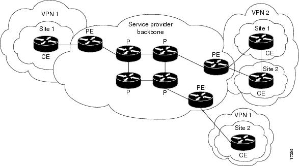 |
| MPLS Virtual Private Networks: VPNs with a Service Provider Backbone |
- Customer (C) devices
A device that is within a customer's network and not directly connected to the service provider's network. C devices are not aware of the VPN.
- Customer Edge device (CE)
A device at the edge of the customer's network which provides access to the PPVPN. Sometimes it's just a demarcation point between provider and customer responsibility. Other providers allow customers to configure it.
- Provider edge device (PE)
A PE is a device, or set of devices, at the edge of the provider network which connects to customer networks through CE devices and present the provider's view of the customer site. PEs are aware of the VPNs that connect through them, and maintain VPN state.
- Provider device (P)
A 'P' device operates inside the provider's core network and does not directly interface to any customer endpoint. It might, for example, provide routing for many provider-operated tunnels that belong to different customers' PPVPNs. While the P device is a key part of implementing PPVPNs, it is not itself VPN-aware and does not maintain VPN state. Its principal role is allowing the service provider to scale its PPVPN offerings, for example, by acting as an aggregation point for multiple PEs. P-to-P connections, in such a role, often are high-capacity optical links between major locations of providers.
VPN Topologies
There are two basic types of VPN networks: site-to-site and remote-access.
 |
| http://computer.howstuffworks.com/vpn3.htm |
The information required to establish the VPN connection, such as the IP address of the telecommuter, changes dynamically depending on the location of the telecommuter.
In the past, corporations supported remote users by using dial-in networks and ISDN.
The Cisco IOS SSL VPN is a technology that provides remote-access connectivity from almost any Internet-enabled location with a web browser and its native SSL encryption (does not require the installation of specialized client software on the end user's computer).
- The primary benefit of SSL VPN is that it is compatible with Dynamic Multipoint VPNs (DMVPNs), Cisco IOS Firewalls, IPsec, intrusion prevention systems (IPSs), Cisco Easy VPN, and Network Address Translation (NAT).
- It has the option of only requiring an SSL-enabled web browser.
SSL VPN currently delivers three modes of SSL VPN access: clientless, thin client, and full client. SSL VPNs allow users to access web pages and services. This includes accessing files, sending and receiving email, and running TCP-based applications without IPsec VPN Client software.
In many cases, IPsec and SSL VPNs are complementary because they solve different problems.
Cisco DMVPN allows branch locations to communicate directly with each other over the public WAN or Internet, such as when using voice over IP (VOIP) between two branch offices, but doesn't require a permanent VPN connection between sites. It enables zero-touch deployment of IPsec VPNs and improves network performance by reducing latency and jitter, while optimizing head office bandwidth utilization.
A site-to-site VPN is created when connection devices on both sides of the VPN connection are aware of the VPN configuration in advance.
It must be statically set up.
The VPN remains static, and internal hosts have no knowledge that a VPN exists. Frame Relay, ATM, GRE, and MPLS VPNs are examples of site-to-site VPNs.
In the past, a leased line or Frame Relay connection was required to connect sites, but because most corporations now have Internet access, these connections can be replaced with site-to-site VPNs.
VPN Solutions
The Cisco VPN product line includes several devices to support remote and site-to-site VPN:
Voice and Video Enabled VPN (V3PN) - Integrates IP telephony, QoS, and IPsec, providing an end-to-end VPN service that helps ensure the timely delivery of latency-sensitive applications such as voice and video.
IPsec stateful failover - Provides fast and scalable network resiliency [rɪ'zɪlɪən(t)sɪ] (syn: flexibility) for VPN sessions between remote and central sites. With both stateless and stateful failover solutions available, such as Hot Standby Router Protocol (HSRP), IPsec stateful failover ensures maximum uptime of mission-critical applications.
Dynamic Multipoint Virtual Private Network (DMVPN) - Enables the auto-provisioning of site-to-site IPsec VPNs, combining three Cisco IOS software features: Next Hop Resolution Protocol (NHRP), multipoint GRE, and IPsec VPN. This combination eases the provisioning (syn: initialization) challenges for customers and provides secure connectivity between all locations.
IPsec and MPLS integration - Enables ISPs to map IPsec sessions directly into an MPLS VPN. This solution can be deployed on co-located edge routers that are connected to a Cisco IOS software MPLS provider edge (PE) network. This approach enables the ISP to securely extend its VPN service beyond the boundaries of the MPLS network by using the public IP infrastructure that securely connects enterprise customer remote offices, telecommuters, and mobile users from anywhere to the corporate network.
Cisco Easy VPN - Simplifies VPN deployment for remote offices and teleworkers. The Cisco Easy VPN solution centralizes VPN management across all Cisco VPN devices, thus reducing the management complexity of VPN deployments.
Cisco ASA
Flexible platform - Offers both IPsec and SSL VPN on a single platform, eliminating the need to provide parallel solutions. In addition to VPN services, Cisco ASA offer application inspection firewall and intrusion prevention services.
Resilient clustering - Allows remote-access deployments to scale cost-effectively by evenly distributing VPN sessions across all Cisco ASA and Cisco VPN 3000 Series Concentrators, without requiring user intervention.
Cisco Easy VPN - Delivers scalable, cost-effective, and easy-to-manage remote-access VPN architecture. Cisco ASA dynamically push the latest VPN security policies to remote VPN devices and clients, making sure that those endpoint policies are up to date before a connection is established.
Automatic Cisco VPN Client updates - Enables Cisco VPN Client software operating on remote desktops to be automatically upgraded.
Cisco IOS SSL VPN - Offers Cisco SSL VPN with clientless and thin client Cisco SSL VPN capabilities.
VPN infrastructure for contemporary applications - Enables converged voice, video, and data across a secure IPsec network by combining robust site-to-site VPN support with rich inspection capabilities, QoS, routing, and stateful failover features.
Integrated web-based management - Provides management of the Cisco ASA using the integrated web-based Cisco Adaptive Security Device Manager (ASDM). Cisco ASDM manages all security and VPN functions of the appliances.
Each Cisco ASA supports a number of VPN peers:
Cisco ASA 5505 - 10 IPsec VPN peers and 25 SSL VPN peers, with a Base license, and 25 VPN peers (IPsec or SSL) with the Security Plus license
Cisco ASA 5510 - 250 VPN peers
Cisco ASA 5520 - 750 VPN peers
Cisco ASA 5540 - 5000 IPsec VPN peers and 2500 SSL VPN peers
Cisco ASA 5550 - 5000 VPN peers
Cisco ASA 5585-X - 10000 VPN peers
Cisco remote-access VPNs can use four IPsec clients:
- Certicom client - A wireless client that is loaded on to wireless personal digital assistants (PDAs) running the Palm or Microsoft Windows Mobile operating systems. Certicom wireless client software allows companies to extend critical enterprise applications, such as email and customer relationship management (CRM) tools, to mobile professionals by enabling handheld devices to connect to corporate VPN gateways for secure wireless access.
- Cisco VPN Client software - Installed on the PC or laptop of an individual, the Cisco VPN Client allows organizations to establish end-to-end, encrypted VPN tunnels for secure connectivity for mobile employees or teleworkers. The Cisco Easy VPN feature allows the Cisco VPN Client to receive security policies from the central site VPN device, the Cisco Easy VPN Server, when a VPN tunnel connection is made, minimizing configuration requirements at the remote location. There are three components of the Cisco Easy VPN solution: Easy VPN Client, Easy VPN Remote, and Easy VPN Server. (Cisco VPN Client: End-of-sale and end-of-life dates)
- Cisco Remote Router VPN Client - A Cisco remote router, configured as a VPN client, that connects small office, home office (SOHO) LANs to the VPN.
- Cisco AnyConnect VPN Client - Next-generation VPN client that provides remote users with secure VPN connections to the Cisco ASA. The Cisco AnyConnect VPN Client is available for the Windows, Mac OS X, and Linux platforms. It is also supported on some smart devices including iPhones, iPads, BlackBerry, and Android smartphones.
To enhance performance and offload the encryption task to specialized hardware, the Cisco VPN family of devices offers hardware acceleration modules:
Advanced integration modules (AIM) - A broad range of Cisco routers can be equipped with AIM. The module is installed inside the router chassis to offload encryption tasks from the router CPU.
Cisco IPsec VPN Shared Port Adapter (SPA) - Delivers scalable and cost-effective VPN performance for Cisco Catalyst 6500 Series Switches and Cisco 7600 Series Routers. Using the Cisco 7600 Series/Catalyst 6500 Series Services SPA Carrier-400, each slot of the Cisco Catalyst 6500 Series Switch or the Cisco 7600 Series Router can support up to two Cisco IPsec VPN SPAs.
Cisco VPN Accelerator Module 2+ (VAM2+) - Provides high performance encryption/compression and key generation services for IPsec VPN applications.
GRE VPN
Generic routing encapsulation (GRE) is a tunneling protocol defined in RFC 1702 and RFC 2784. It was originally developed by Cisco Systems for creating a virtual point-to-point link to Cisco routers at remote points over an IP internetwork.
GRE Tunneling Protocol
- Encapsulates a wide variety of protocol packet types inside IP tunnels
- Creates a virtual point-to-point link to Cisco routers at remote points over an IP internetwork
- Uses IP for transport
- Uses an additional header to support IP multicasting and any other OSI Layer 3 protocol as payload
- GRE tunnels are stateless (meaning that the router will always assume a GRE tunnel is up once it’s up (until when the router tries to transmit some packets and it fails). The router doesn’t know about the status of the tunnel unless we use keepalives. Keepalives are simple Hellos to test the reachability by sending a packet from point A to point B and see if it returns.)
- GRE does not include any strong security mechanisms to protect its payload
- GRE encapsulates the entire original IP packet with a standard IP header and GRE header. A GRE tunnel header contains at least two 2-byte mandatory fields (GRE flag, Protocol type )
 |
| GRE Encapsulation |
GRE uses a protocol type field in the GRE header to support the encapsulation of any OSI Layer 3 protocol.
The GRE header, together with the tunneling IP header, creates at least 24 bytes (per packet) of additional overhead for tunneled packets.

GRE tunnel is up and the protocol is up if:
- Tunnel source and destination are configured
- Tunnel destination is in routing table
- GRE keepalives are received (if used)
- GRE is the default tunnel mode.
IPsec
IPsec is an IETF standard (RFC 2401-2412) that defines how a VPN can be configured using the IP addressing protocol.
IPsec:
- It is a framework of open standards which is algorithm-independent.
- It provides data confidentiality, data integrity, and origin authentication.
- works at the Network Layer, protecting and authenticating IP packets between participating IPsec devices (peers),
- protect virtually all application traffic because the protection can be implemented from Layer 4 through Layer 7,
- have a plaintext Layer 3 header, so there are no issues with routing,
- works over all Layer 2 protocols, such as Ethernet, ATM, Frame Relay, Synchronous Data Link Control (SDLC), and High-Level Data Link Control (HDLC).
 |
| IPsec Framework |
The two main IPsec framework protocols are AH and ESP.
- AH (Authentication Header) (which is IP protocol 51) provides the following: All data in plaintext, Authentication, Integrity
- ESP (Encapsulating Security Payload) (which is IP protocol 50) provides the following: Encryption (All data is encrypted), Authentication, Integrity
ESP and AH can be applied to IP packets in two different modes, transport mode and tunnel mode:
- Transport Mode, security is provided only for the Transport Layer of the OSI model and above. Transport mode protects the payload of the packet but leaves the original IP address in plaintext.
- Tunnel mode provides security for the complete original IP packet. The original IP packet is encrypted and then it is encapsulated in another IP packet. This is known as IP-in-IP encryption.
New IP header - is portion of the packet that is not authenticated
- DES - Uses a 56-bit key, ensuring high-performance encryption. DES is a symmetric key cryptosystem. LESS SECURE.
The default IKE policy value for encryption is DES.
- 3DES - A variant of the 56-bit DES. 3DES uses three independent 56-bit encryption keys per 64-bit block, providing significantly stronger encryption strength over DES. 3DES is a symmetric key cryptosystem.
- AES - Provides stronger security than DES and is computationally more efficient than 3DES. AES offers three different key lengths: 128 bits, 192 bits, and 256 bits. AES is a symmetric key cryptosystem.
- Software-Optimized Encryption Algorithm (SEAL) - A stream cipher developed in 1993 by Phillip Rogaway and Don Coppersmith, which uses a 160-bit key. SEAL is a symmetric key cryptosystem. MOST SECURE.
3) Integrity
Hashed Message Authentication Codes (HMAC) is a data integrity algorithm that guarantees the integrity of the message using a hash value.
There are two common HMAC algorithms:
- HMAC-Message Digest 5 (HMAC-MD5) - Uses a 128-bit shared-secret key. The variable-length message and 128-bit shared secret key are combined and run through the HMAC-MD5 hash algorithm. The output is a 128-bit hash.
- HMAC-Secure Hash Algorithm 1 (HMAC-SHA-1) - Uses a 160-bit secret key. The variable-length message and the 160-bit shared secret key are combined and run through the HMAC-SHA-1 hash algorithm. The output is a 160-bit hash.
HMAC-SHA-1 is considered cryptographically stronger than HMAC-MD5. It is recommended when slightly superior security is important.
4) Authentication
There are two primary methods of configuring peer authentication.
- PSK (Pre-shared Keys) - A pre-shared secret key value is entered into each peer manually and is used to authenticate the peer. At each end, the PSK is combined with other information to form the authentication key. Each peer must authenticate its opposite peer before the tunnel is considered secure. Pre-shared keys are easy to configure manually but do not scale well, because each IPsec peer must be configured with the pre-shared key of every other peer with which it communicates.
- RSA signatures - The exchange of digital certificates authenticates the peers. The local device derives a hash and encrypts it with its private key. The encrypted hash is attached to the message and is forwarded to the remote end and acts like a signature. At the remote end, the encrypted hash is decrypted using the public key of the local end. If the decrypted hash matches the recomputed hash, the signature is genuine. Each peer must authenticate its opposite peer before the tunnel is considered secure.
5) Secure Key Exchange
Encryption algorithms such as DES, 3DES, and AES as well as the MD5 and SHA-1 hashing algorithms require a symmetric, shared secret key to perform encryption and decryption.
The Diffie-Hellman (DH) key agreement is a public key exchange method that provides a way for two peers to establish a shared secret key that only they know, even though they are communicating over an insecure channel.
There are several DH groups:
- DH groups 1, 2, and 5 support exponentiation over a prime modulus with a key size of 768 bits, 1024 bits, and 1536 bits, respectively. These groups are not recommended for use after 2012.
- DH groups 14, 15, and 16 use larger key sizes with 2048 bits, 3072 bits, and 4096 bits, respectively, and are recommend for use until 2030.
- DH groups 19, 20 and 24 support Elliptical Curve Cryptography (ECC), which reduces the time needed to generate keys. With respective key sizes 256 bits, 384 bits, and 2048 bits. DH group 24 is preferred for longevity of use.
Newer Cisco IOS versions support more advanced DH groups.
IKE (Internet Key Exchange)
Internet Key Exchange (IKE or IKEv2) is the protocol used to set up a security association (SA) in the IPsec protocol suite. IKE builds upon the Oakley protocol and ISAKMP. IKE uses X.509 certificates for authentication which are either pre-shared or distributed using DNS (preferably with DNSSEC) and a Diffie–Hellman key exchange to set up a shared session secret from which cryptographic keys are derived.In addition, a security policy for every peer which will connect must be manually maintained.
Terminology
- IPSec (Internet Protocol Security) is a technology protocol suite for securing Internet Protocol (IP) communications by authenticating and encrypting each IP packet of a communication session. IPsec also includes protocols for establishing mutual authentication between agents at the beginning of the session and negotiation of cryptographic keys to be used during the session.
It can be used in protecting data flows between a pair of hosts (host-to-host), between a pair of security gateways (network-to-network), or between a security gateway and a host (network-to-host).
- SA (Security Association) is the establishment of shared security attributes between two network entities to support secure communication. An SA may include attributes such as: cryptographic algorithm and mode; traffic encryption key; and parameters for the network data to be passed over the connection. An SA is a simplex (one-way channel) and logical connection which endorses and provides a secure data connection between the network devices.
- The Oakley Key Determination Protocol is a key-agreement protocol that allows authenticated parties to exchange keying material across an insecure connection using the Diffie-Hellman key exchange algorithm.
- The Diffie–Hellman key exchange method allows two parties that have no prior knowledge of each other to jointly establish a shared secret key over an insecure communications channel.
- The shared secret can be a password, a passphrase, a big number or an array of randomly chosen bytes
- ISAKMP (Internet Security Association and Key Management Protocol) is a protocol defined by RFC 2408 for establishing Security Associations (SA) and cryptographic keys in an Internet environment.
- X.509 is an ITU-T standard for a public key infrastructure (PKI) and Privilege Management Infrastructure (PMI).
The IPsec VPN solution negotiates key exchange parameters, establishes a shared key, authenticates the peer, and negotiates the encryption parameters.
The negotiated parameters between two devices are known as a security association (SA).
IPsec uses the Internet Key Exchange (IKE) protocol to establish the key exchange process. Instead of transmitting keys directly across a network, IKE calculates shared keys based on the exchange of a series of data packets.
This disables a third party from decrypting the keys even if the third party captured all exchanged data that is used to calculate the keys.
IKE is layered on UDP and uses UDP port 500 to exchange IKE information between the security gateways. UDP port 500 packets must be permitted on any IP interface involved in connecting a security gateway peer.
IKE is defined in RFC 2409.
IKE was originally defined in November 1998 by the Internet Engineering Task Force (IETF) in a series of publications (Request for Comments) known as RFC 2407, RFC 2408, and RFC 2409.It is a hybrid protocol, combining:
- RFC 2407 defined The Internet IP Security Domain of Interpretation for ISAKMP.
- RFC 2408 Internet Security Association and Key Management Protocol (ISAKMP)
- RFC 2409 defined The Internet Key Exchange (IKE) [6]
IKE was updated to version two (IKEv2) in December 2005 by RFC 4306.
Some open details were clarified in October 2006 by RFC 4718.
These two documents plus additional clarifications were combined into the updated IKEv2 RFC 5996 which was published in September 2010.
- the ISAKMP (Internet Security Association and Key Management Protocol) and,
- the Oakley and Skeme key exchange methods.
ISAKMP defines the message format, the mechanics of a key-exchange protocol, and the negotiation process to build an SA for IPsec.
Oakley and Skeme have five defined key groups. Of these groups, Cisco routers support Group 1 (768-bit key), Group 2 (1024-bit key), and Group 5 (1536-bit key).
An alternative to using IKE is to manually configure all parameters required to establish a secure IPsec connection. This process is impractical because it does not scale.
In order to properly secure things, you first (phase 1) need to agree on exactly how you are going to exchange the traffic encrypting/authenticating keys, and what the lifetime is and what the change mechanism is). If you can't agree on using the same pieces/methods, then you can't really proceed, can you?
Once you decide on what you'll use to exchange keys, then you move to the actual WORK part (phase 2) where you are using a key to encrypt/authenticate traffic based on netgotiated parameters.
If your agreements on policy fail here, you'll see a phase 2 failure.
To establish a secure communication channel between two peers, the IKE protocol executes two phases:
Phase 1 - Two IPsec peers perform the initial negotiation of SAs (negotiate IKE policy sets, authenticate the peers, and set up a secure channel between the peers).
It can be implemented in
- main mode (longer, initial contact) or,
- aggressive mode (after initial contact).
An IKE session begins with a router (the initiator) sending a proposals to another router (the responder).
There are five parameters that must be coordinated during IKE phase 1:
(to remember it is used abbreviation HAGLE)
1) H - HASH: (MD5 or SHA-1)
2) A - AUTHENTICATION: IKE authentication algorithm (preshare key a.k.a PSK, RSA signatures)
3) G - GROUP: Diffie-Hellman Group (version 1, 2 or 5)
4) L - LIFETIME: IKE tunnel lifetime (time and/or byte count)
5) E - ENCRYPTION: IKE encryption algorithm (DES, 3DES, or AES)
This tunnel (once established) is not going to be used to forward user packets, but rather only to protect management traffic related to the VPN between the two routers. Packets such as a keepalive message to verify that the VPN tunnel is still working are an example of traffic that these two routers send across the IKE Phase 1 tunnel directly to each other.
This IKE Phase 1 tunnel is not used to encrypt or protect the end user’s packets.
This second tunnel is called the IKE Phase 2 tunnel, it is also commonly referred to as the IPsec tunnel.
Immediately after the IKE Phase 1 tunnel is established, the routers immediately begin to establish the IKE Phase 2 tunnel.
# show crypto session (IKE Session (tunnels) up/down)
# show crypto isakmp sa (ISAKMP SA: peers, stutus)
# show crypto isakmp policy (HAGLE)
Phase 2 - SAs are negotiated by the IKE process (ISAKMP) on behalf (in name of) of IPsec. It can be negotiated in quick mode. The purpose of IKE Phase 2 is to negotiate the IPsec security parameters that will be used to secure the IPsec tunnel. IKE Phase 2 is called quick mode and can only occur after IKE has established the secure tunnel in Phase 1.
IKE Phase 2 performs the following functions:
- Negotiates IPsec security parameters, known as IPsec transform sets.
- Establishes IPsec SAs
- Periodically renegotiates IPsec SAs to ensure security
- Optionally performs an additional DH exchange.
Transform set is a group of policies that the routers establishing the VPN need to agree on.
Five parameters must be coordinated during quick mode between IPsec peers:
1) IPsec protocol (ESP or AH)
2) IPsec encryption type (DES, 3DES, or AES)
3) IPsec authentication (MD5 or SHA-1)
4) IPsec mode (tunnel or transport)
5) IPsec SA lifetime (seconds)
Three exchanges transpire during IKE Phase 1.
These are referred to as the first, second, and third exchanges. The three exchanges of IKE Phase 1 occur during what is called main mode.
First Exchange - between the initiator and the responder establishes the basic security policy.
Peers negotiate and agree on the algorithms and hashes that are used to secure the IKE communications. Rather than negotiate each protocol individually, the protocols are grouped into sets, called IKE policy sets. The IKE policy sets are exchanged first.
Policy set numbers are only locally significant to a VPN device.
Second Exchange - creates and exchanges the DH public keys between the two endpoints.
Third Exchange - Each end device must authenticate the other end device before the communication path is considered secure. The last exchange of IKE Phase 1 authenticates the remote peer.
# show crypto ipsec sa (IPSec peer, packets, crypto )
# show crypto ipsec transform-set (IPSec encryption options)
# show crypto map (IPSec config: crypto map, interface, peer)
Aggressive mode is another option for IKE Phase 1.
Aggressive mode is faster than main mode because there are fewer exchanges. Aggressive mode compresses the IKE SA negotiation phases into one exchange with three packets, whereas main mode requires three exchanges with six packets.
Aggressive mode packets include:
First packet - The initiator packages everything needed for the SA negotiation in the first message, including its DH public key.
Second packet - The recipient responds with the acceptable parameters, authentication information, and its DH public key.
Third packet - The initiator then sends a confirmation that it received that information.
Aggressive mode negotiation is quicker, and the initiator and responder IDs pass in plaintext.
After the IKE SA is established, Phase 2 negotiation begins.
So, we could say we have:
- one IKE Phase 1 bidirectional tunnel used for management between the two VPN peers,
- two IKE Phase 2 unidirectional tunnels used for encrypting and decrypting end-user packets. These tunnels are often referred to as the security agreements between the two VPN peers. Many times, these agreements are called security associations (SA) . Each SA is assigned a unique number for tracking.
The routing decision happens before IPsec is implemented.
IPSEC Authentication
There are 3 common way to authentication in IPSec:
1. pre-share key
IKE peers authenticate each other by computing and sending keyed hash of data that include the pre-shared key, if the receiving peer is able to create the same hash using its pre-shared key <== authenticate
* easier
* do not scale well
2. RSA signature
Uses a digital signature
Each device digitally sign a set of date and sent it
Uses CA to generate a unique ID digital certificate
Initiator and responder using RSA signature send their own:
- ID value (IDi, IDr)
- identity digital certificate
- RSA signature value
3. RSA Encryption
Uses RSA encryption public key cryptography
Requires each party to generate a pseudorandom number (nounces), encrypt it with the other party’s RSA public key.
Authentication occurs when each party decrypt the other party nonce with local private key
Configure Site-to-Site VPN
Tasks to Configure IPsec:
Task 1: Ensure that ACLs configured on interfaces are compatible with the IPsec configuration.
Ensure that protocols 50 (ESP), 51 (AH) and UDP port 500 (ISAKMP) traffic are not blocked by incoming ACLs on interfaces used by IPsec.
access-list acl permit ahp source wildcard destination wildcardTask 2: Create an ISAKMP (IKE) policy
access-list acl permit esp source wildcard destination wildcard
access-list acl permit udp source wildcard destination wildcard eq isakmp
R1(config)# crypto isakmp policy 100 <- policy numbers are locally significant and do not have to match between IPsec peersA match is made when both policies from the two peers contain the same encryption, hash, authentication, DH parameter values, and when the policy of the remote peer specifies a lifetime less than or equal to the lifetime of the policy that is being compared. If the lifetimes are not identical, the shorter lifetime from the remote peer policy is used.
R1(config-isakmp)# authentication pre-share
R1(config-isakmp)# encryption aes 256
R1(config-isakmp)# group 5
R1(config-isakmp)# hash md5
R1(config-isakmp)# lifetime 86400
If an acceptable match is not found, ISAKMP refuses negotiation, and IPsec is not established.
Configure a PSK:
crypto isakmp key keystring address peer-addressBy default, the ISAKMP identity is set to use the IP address. To use the hostname parameter, the ISAKMP identity must be configured to use the host name with the
crypto isakmp key keystring hostname hostname
crypto isakmp identity hostname global configuration mode command.
In addition, DNS must be accessible to resolve the hostname.
Task 3: Configure an IPsec transform set
- A transform set is a combination of individual IPsec transforms that are designed to enact ([ɪ'nækt] , постановлять ) a specific security policy for traffic.
- A transform set can have one AH transform and up to two ESP transforms.
- Multiple transform sets can be configured. Then one or more of these transform sets can be specified in a crypto map entry.
- Transform sets are negotiated during IKE Phase 2.
- IPsec peers search for a transform set that matches at both ends and agree on one unidirectional transform proposal per SA.
crypto ipsec transform-set transform-set-name transform1 [transform2] [transform3] [transform4]When ISAKMP is not used to establish SAs, a single transform set must be used. In this instance, the transform set is not negotiated.
Task 4: Create a crypto ACL
- Outbound indicates the data flow to be protected by IPsec.
- Inbound filters out and discards traffic that should have been protected by IPsec.
- The crypto ACL is associated with a crypto map, which in turn is assigned to a specific interface.
Task 5: Create and apply the crypto map:
- ACL to be used
- Remote VPN peers
- Transform set to be used
- Key management method
- SA lifetime
- Applies the crypto map to outgoing interface
Only one crypto map can be set to a single interface.
Multiple peers can be specified for redundancy.
Multiple interfaces can share the same crypto map set if the same policy is applied to multiple interfaces.
crypto map map-name seq-num ciscoCrypto map config
crypto map map-name seq-num ipsec-manual
! ipsec-manual - Indicates that ISAKMP will not be used to establish the IPsec SAs.
crypto map map-name seq-num ipsec-isakmp [dynamic dynamic-map-name]
! ipsec-isakmp - Indicates that ISAKMP will be used to establish the IPsec SAs.
! dynamic - (Optional) Specifies that this crypto map entry references a preexisting static crypto map.
! If this keyword is used, none of the crypto map configuration commands are available.
no crypto map map-name [seq-num]
crypto map MyMap 1 ipsec-isakmpConfigure the crypto map on the outgoing interface.
set peer 10.102.0.2
set security-association lifetime seconds 190
set transform-set MySet
match address 101
R1(config)# interface S0/0/0
R1(config-if)# crypto map VPN-MAP
Sample of IPSec config from R1 to R3
!
hostname R1
!
interface Serial0/0/0
ip address 10.1.1.2 255.255.255.252
crypto map VPN-MAP
!
access-list 110 permit ip 192.168.1.0 0.0.0.255 192.168.3.0 0.0.0.255
!
! ISAKMP Phase 1
crypto isakmp policy 10
encryption aes
authentication pre-share
group 2
crypto isakmp key vpnpa55 address 10.2.2.2
!
! ISAKMP Phase 2
crypto ipsec transform-set VPN-SET esp-3des esp-sha-hmac
crypto map VPN-MAP 10 ipsec-isakmp
description VPN connection to R3
set peer 10.2.2.2
set transform-set VPN-SET
match address 110
!
Troubleshooting IPSec commands
show crypto map - verifies configurations and shows the SA lifetimeImplementing Remote-Access VPNs
show crypto isakmp policy - display configured IKE policies and the default IKE policy settings. This command is useful because it reveals all ISAKMP (IKE) configuration information (encryption algorithm, hash algorithm, authentication method, and Diffie-Hellman group configured, as well as default settings)
show crypto ipsec sa - If the output indicates that an SA is established, the rest of the configuration is assumed to be working. Within the output, the pkts encrypt and pkts decrypt values indicate that traffic is flowing through the tunnel.
show crypto ipsec transform-set - show all configured transform sets
debug crypto isakmp
debug crypto ipsec
Telecommuting is sometimes referred to as teleworking.
Telecommuting Benefits:
- Organizational benefits:
--- Continuity of operations
--- Increased responsiveness
--- Secure, reliable, and manageable access to information
--- Cost-effective integration of data, voice, video, and applications
--- Increased employee productivity, satisfaction, and retention
- Social benefits:
--- Increased employment opportunities for marginalized groups
--- Less travel and commuter related stress
- Environmental benefits:
--- Reduced carbon footprints, both for individual workers and organizations
There are two primary methods for deploying remote-access VPNs:
1) Secure Sockets Layer (SSL)
2) IP Security (IPsec)
When security is an issue, IPsec is the superior choice. If support and ease of deployment are the primary issues, consider SSL.
IPsec and SSL VPN are complementary because they solve different problems. Depending on its needs, an organization can implement one or both.
Cisco remote-access VPN solutions offer both technologies integrated on a single platform with unified management.
Cisco IOS SSL VPN technology provides remote-access connectivity from almost any Internet-enabled location using a web browser and its native SSL encryption.
- An SSL VPN does not require a software client to be preinstalled on the endpoint host,
- Protection against viruses, worms, spyware, and hackers,
- Simple, flexible, and cost-effective licensing. SSL uses a single license,
- Single device for both SSL VPN and IPsec VPN.
SSL VPNs provide different types of access:
- Clientless, the remote user accesses the internal or corporate network using a web browser on the client machine. No other software is required, eliminating many support issues. Not all client/server applications are accessible to SSL clients.
- Thin client, sometimes called TCP port forwarding, assumes that the client application uses TCP to connect to a well-known server and port. The remote user downloads a Java applet by clicking the link provided on the portal page. The Java applet acts as a TCP proxy on the client machine for the services configured on the SSL VPN gateway. The Java applet starts a new SSL connection for every client connection. Enable remote access to TCP-based applications such as POP3, SMTP, IMAP, Telnet, and SSH.
- Full client, enables complete access to the corporate network over an SSL VPN tunnel, which is used to move data at the Network (IP) Layer. A Java applet is downloaded to handle the tunneling between the client host and the SSL VPN gateway.
Considerations deploing SSL VPNs:
- The SSL VPN process is fairly CPU and memory intensive.
- Need to determine the size of the SSL VPN deployment, especially the number of simultaneous users that will connect to gain network access.
- The configuration of SSL VPNs is beyond the scope of this course. (visit cisco.com)
The Cisco Easy VPN
This solution feature offers flexibility, scalability, and ease of use for site-to-site and remote-access VPNs.
* Negotiates tunnel parameters
* Establishes tunnels according to set parameters
* Authenticates users by usernames, group names, and passwords
* Manages security keys for encryption and decryption
* Authenticates, encrypts, and decrypts data through the tunnel
It consists of three components:
- Cisco Easy VPN Server - A Cisco IOS router or Cisco ASA Firewall acting as the VPN head-end device in site-to-site or remote-access VPNs.
- Cisco Easy VPN Remote - A Cisco IOS router or Cisco ASA Firewall acting as a remote VPN client.
- Cisco VPN Client - An application supported on a PC used to access a Cisco VPN server.
When a client connects to a server, the negotiation to secure the VPN occurs:
1. The VPN client initiates the IKE Phase 1 process.
2. The VPN client establishes an ISAKMP SA.
3. The Easy VPN Server accepts the SA proposal. Always configure the most secure policies first.
4. The Easy VPN Server initiates a username and password challenge.
5. The mode configuration process is initiated.
6. The reverse route injection (RRI) process is initiated. RRI ensures that a static route is created on the Cisco Easy VPN Server for the internal IP address of each VPN client.
7. IPsec quick mode completes the connection. The connection is complete after IPsec SAs have been created.
Configuration with CCP:
IOS Router as Easy VPN Server Using Configuration Professional Configuration Example
1) Specify the router interface where the VPN connection will terminate and the authentication method
(e.g., pre-shared keys, digital certificates, or both). [e.g. = exempli gratia, Latin: "for example"]
2) Add a custom IKE Policy specifying these required parameters:
- Interface on which client connections terminate
- IKE policy
- Authentication (PRE_SHARE or RSA_SIG)
- D-H group (group1, group2, or group5)
- Encryption algorithm (DES, 3DES or AES)
- Hash (SHA_1 or MD5)
- IKE lifetime
3) CCP provides a default transform set. Use the default or create a new IPsec transform set configuration using these parameters:
- Transform set name
- Encryption algorithm (DES, 3DES, AES, or SEAL)
- HMAC (SHA_1 or MD5)
- Optional compression
- Mode of operation (tunnel or transport)
4) The location where Easy VPN group policies can be stored:
- Local - All groups are in the router configuration in NVRAM.
- RADIUS - The router uses the RADIUS server for group authorization.
- RADIUS and Local - The router can look up policies stored in an AAA server database that can be reached via RADIUS.
Extra Information about VPNs
I) Protocols used to enable remote access VPNs:
- IPsec
- The Secure Sockets Layer (SSL)
- The Layer Two Forwarding (L2F) Protocol—L2F is a Cisco proprietary protocol that is designed to allow the tunneling of PPP (or Serial Line Interface Protocol [SLIP]) frames between a NAS and a VPN gateway device located at a central site. Remote access users connect to the NAS, and the PPP frames from the remote access user are then tunneled over the intervening network to the VPN (home) gateway.
- The Point-to-Point Tunneling Protocol (PPTP)—PPTP is a protocol that was
developed by a consortium of vendors, including Microsoft, 3Com, and Ascend
Communications. Like L2F, PPTP allows the tunneling of remote access client PPP
frames between a NAS and a VPN gateway/concentrator. PPTP also allows a tunnel
to be set up directly from a remote access client to a VPN gateway/concentrator.
PPP encapsulated packets carried over PPTP tunnels are often protected using Microsoft Point-to-Point Encryption (MPPE). - The Layer 2 Tunneling Protocol versions 2 and 3 (L2TPv2/L2TPv3)—L2TP is an
Internet Engineering Task Force (IETF) standard and combines the best features of
L2F and PPTP. In a remote access environment, L2TP allows either tunneling of
remote access client PPP frames via a NAS to a VPN gateway/concentrator or
tunneling of PPP frames directly from the remote access client to the VPN gateway/
concentrator.
L2TP has limited intrinsic security, and so L2TP tunnels are often protected using IPsec.
Service provider provisioned site-to-site VPNs (PPVPN) fall into one of three categories:
Layer 1 VPNs, Layer 2 VPNs, and Layer 3 VPNs.
Layer 2 and Layer 3 site-to-site VPN types are described in the sections that follow.
1) The development of L1VPNs is in its relative infancy, and so L1VPNs are not discussed further in this book.
2) Layer 2 VPNs
Layer 2 site-to-site VPNs (L2VPN) can be provisioned between switches, hosts, and routers and allow data link layer connectivity between separate sites. Communication between customer switches, hosts, and routers is based on Layer 2 addressing, and PE devices perform forwarding of customer data traffic based on incoming link and Layer 2 header information (such as MAC address, Frame Relay Data Link Connection Identifier [DLCI], and so on).
There are two categories of provider provisioned L2VPN:
- Point-to-point (P2P) circuit-based VPNs—P2P-based VPNs are also known as Virtual Private Wire Service (VPWS) VPNs and are constructed using, for example, Draft Martini (MPLS) or L2TPv3 pseudowires (emulated circuits). It is worth noting that VPWS was formerly known as Virtual Leased Line Service (VLL service or VLLS).
- Multipoint-to-multipoint (M2M) VPNs—M2M VPNs come in two varieties:
Virtual Private LAN Service (VPLS) VPNs
IP-Only LAN Service (IPLS) VPNs
3) Layer 3 VPNs
Layer 3 site-to-site VPNs (L3VPN) interconnect hosts and routers at separate customer sites.
These customer hosts and routers communicate based on Layer 3 (network layer) addressing, and PE devices forward customer traffic based on incoming link, and on addresses contained in the (outer) IP header.
There are two overall types of L3VPN:
- PE-based VPNs—In a PE-based L3VPN, PE devices participate in customer network routing and forward traffic based on customer network addressing.
Customer traffic is (usually) forwarded between PE devices over VPN tunnels that may take the form of (MPLS) LSPs, IPsec tunnels, L2TPv3 tunnels, or GRE tunnels, for example. In this case, CE devices are not aware that they are participating in a VPN.
- CE-based VPNs—In a CE-based L3VPN, PE devices do not participate in (and are unaware of) customer network routing and forward customer traffic based on globally unique addressing. In this case, tunnels are configured between CE devices using protocols such as GRE and IPsec.
III) OpenVPN
Here is a brief summary of the principle behind OpenVPN:
Imagine you had a direct physical wire (i.e. a long cable) connecting two computers (A and B) at different locations.
On each computer there would be a /dev/longcable which would be a network device. You could route IP traffic over it, and do everything you could normally do with a network device.
Basically a tun device is like having a /dev/longcable except the OpenVPN daemon is the program that connects the /dev/longcable on computer A with the /dev/longcable on computer B so that you can use the internet rather than a real physical cable. But in this case it is called /dev/tun or whatever your OS prefers to call them.
Now the mechanism by which OpenVPN connects /dev/tun on computer A with /dev/tun on computer B is this: It simply creates an encrypted UDP connection over the internet between A and B and forwards traffic between /dev/tun on A with /dev/tun on B. Because of the clever way in which the tun and tap drivers were designed, it is possible for a program running entirely in user-space to effect this link, allowing OpenVPN to be a portable cross-platform daemon (like SSH), rather than an OS-specific kernel module (like IPSec).
The difference between a tun and tap device is this: a tun device is a virtual IP point-to-point device and a tap device is a virtual ethernet device.
So getting back to the "long cable" analogy, using a tun device would be like having a T1 cable connecting the computers and using a tap device would be like having an ethernet network connecting the two computers. People who are running applications that need the special features of ethernet (which won't work on an IP-only network) will often bridge their physical local ethernet with a tap device (using a utility such as brctl on Linux), then VPN the tap device to another similar setup at the other end. This allows OpenVPN to route ethernet broadcasts and non-IP protocols such as Windows NetBios over the VPN. If you don't need the special features of ethernet (such as bridging capability), it's better to use a tun device.
Tun and tap devices can be interconnected to create a complex routing topology. Some people have created multi-node WAN networks over tap devices and actually run DHCP over the VPN so that clients can log into the virtual ethernet and request an IP address. I've even heard of people using Linux advanced routing to run OSPF (a kind of dynamic routing protocol) over the VPN WAN to allow for dynamic, fault-tolerant routing. They sky is the limit as far as the complexity of network you can build, but the basic building block is a VPN daemon such as OpenVPN connecting tun or tap devices on two different machines.